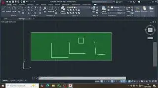
Autocad 2d drawing mechanical Part-3
Автор: arbaaz khan
Загружено: 2026-01-12
Просмотров: 11
Описание:
Mechanical 2D drawing in AutoCAD involves using specialized toolsets and precise drafting commands to create technical blueprints for parts, assemblies, and machinery. While standard AutoCAD supports general 2D drafting, AutoCAD Mechanical is specifically designed for this field, including libraries of over 700,000 standard parts and features for automated bill of materials (BOM) generation.
Core Drafting Commands
For 2D mechanical design, the following fundamental commands are used to build geometry:
Draw Commands: LINE (L), CIRCLE (C), and ARC for basic geometry.
Modify Commands: TRIM (TR) to remove excess segments, OFFSET (O) for parallel lines or concentric circles, and FILLET (F) to create rounded corners.
Precision Tools: OSNAP (Object Snap) to lock onto specific points like centers or quadrants, and ORTHO to restrict movement to horizontal or vertical axes.
Replication: MIRROR (MI) for symmetrical parts and ARRAY (AR) to create multiple copies in rectangular or polar patterns (e.g., holes in a flange).
Step-by-Step Workflow Example
Typical 2D mechanical workflows follow a structured approach:
Setup: Set drawing units (usually mm or inches) and create Layers to separate center lines, hidden lines, and final object outlines.
Reference Lines: Establish center lines and base points to define the part's orientation.
Core Geometry: Draw primary circles and lines based on the part's main dimensions.
Detailing: Use FILLET or CHAMFER for edge treatments and ARRAY for repetitive features like bolts.
Annotation: Apply dimensions (linear, diameter, radial) and technical notes to finalize the blueprint.
Повторяем попытку...

Доступные форматы для скачивания:
Скачать видео
-
Информация по загрузке:


![[Плейлист] Когда вы не хотите думать ни о чем | Уютная расслабляющая джазовая музыка на заднем фоне](https://image.4k-video.ru/id-video/Llour2YvsiI)