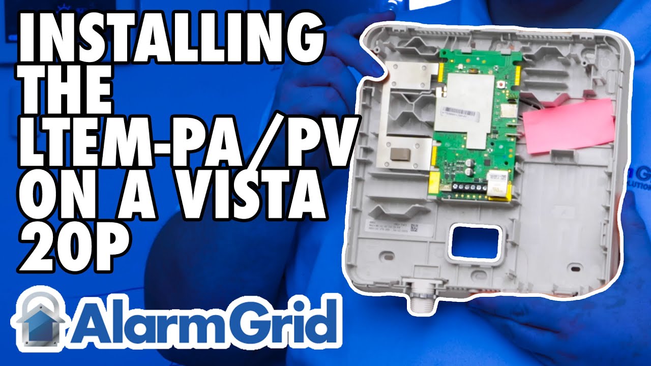
LTEM-PA or LTEM-PV: Installation with a Vista 20P
Автор: Alarm Grid
Загружено: 2022-06-17
Просмотров: 7101
Описание:
In this video, Griffin from Alarm Grid shows you how to connect a Resideo LTEM-PV (or LTEM-PA) to a VISTA-20P panel when the communicator is using its own power adapter. When any of the add-on modules are used, such as the PROWIFIZW, PRODCM Dialer Capture Module, or a separate LTE module, then the LTEM-PV or LTEM-PA should be connected to its own power adapter and should have its own battery.
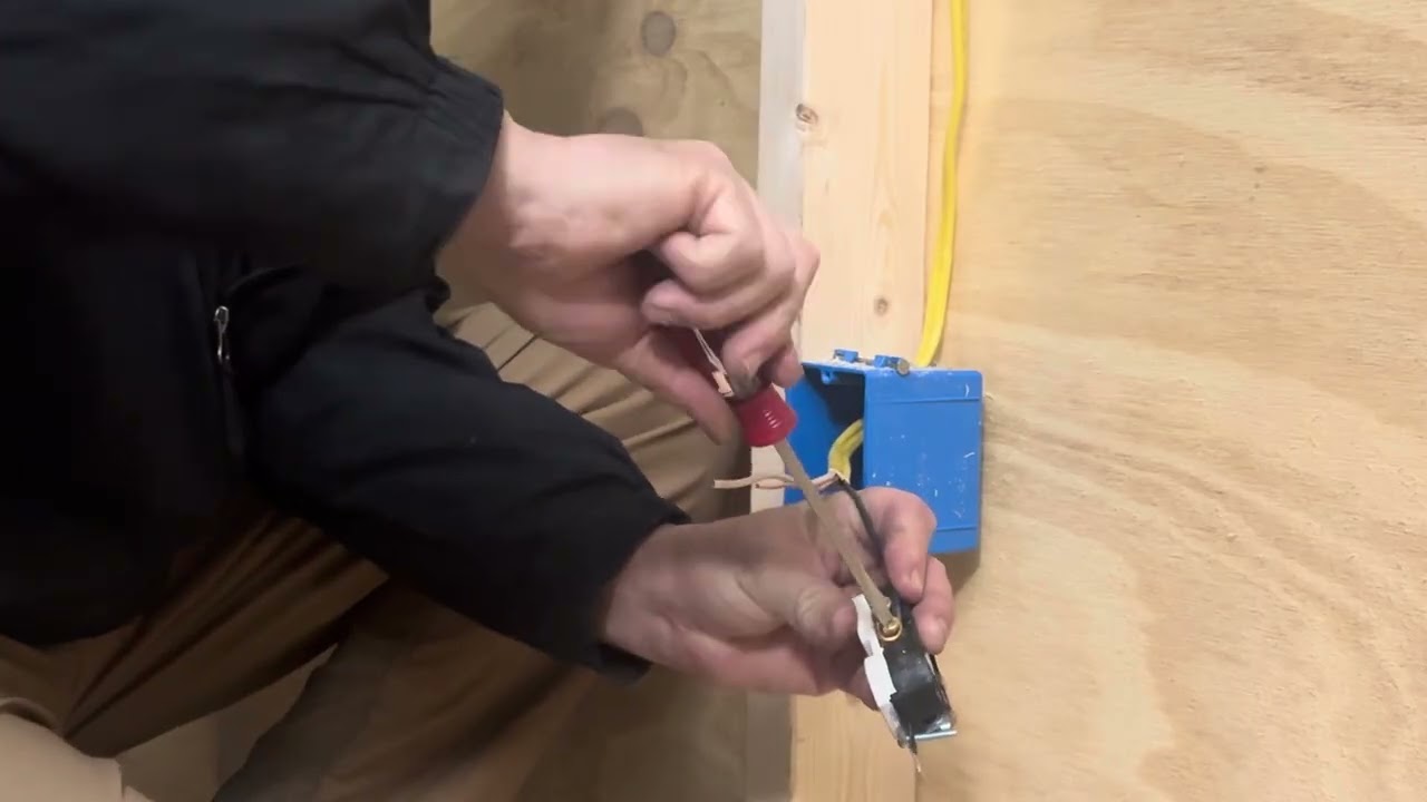
Start by making sure all equipment is powered down. This includes both battery and primary power for both the VISTA-20P and the LTEM-PV or LTEM-PA. Be sure the transformer and battery for the panel are both unplugged, and that the DC Power Adapter and battery for the communicator are also disconnected.
One thing we don't touch on in this video, that is important, is the routing of wire. You want to be sure that any wires that will traverse to the outside of the LTEM-PV or LTEM-PA are routed in such a way that the cover can be securely attached once your work is complete. This means either routing the wire through the provided hole at the bottom of the communicator, as shown by Griffin in the video, routing it through the back of the communicator and fishing the wire through the wall, or using one of the plastic knock-outs in the side of the backplate to route the wires so that the cover can be properly seated.
Whether you use an LT-Cable, as suggested in the video, or just a pair of wires you have laying around, be sure to observe proper polarity between the DC Power Adapter and the LTEM-PV or LTEM-PA. Connect the Black wire to the terminal marked Negative (-) on the power adapter, and connect the Red wire to the terminal marked Positive (+). At the Communicator end, connect the Black wire to (GND), and connect the Red wire to (+9VDC).
The LTEM-PV and LTEM-PA come with a wiring harness to allow for an easy connection between the communicator and the alarm panel. The plastic header is keyed, so you can't plug it in the wrong way. This harness offers a precut length of wire. In some cases, this won't be long enough, and you'll either have to splice your own wire into the harness wire ends, or you'll have to use the terminals on the communicator, instead of the harness, and cut your own wire. If you do need to use your own wire, be sure to make the proper connections at both ends, the communicator and the alarm panel. The FAQ linked at the bottom of this description shows you both ways of wiring, in detail.
Connect the harness to the port on the communicator, route the wires properly so that the cover can be securely fastened to the communicator when you're finished, and make your connections at the panel. The Black wire from the harness connects to Panel Terminal 4, the Yellow wire from the harness connects to Panel Terminal 7, and the Green wire from the harness connects to Panel Terminal 6.
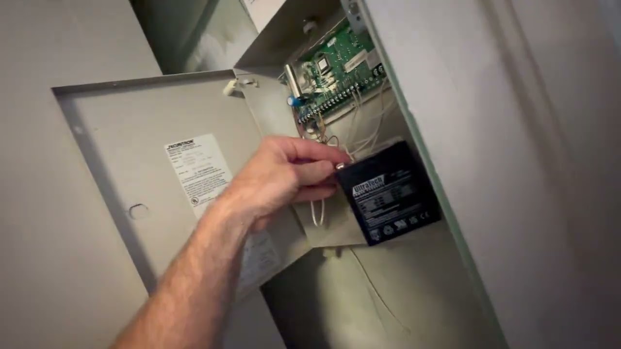
Once all wires are connected, start by connecting the battery to the LTEM-PV or LTEM-PA, then plug in the DC Power Adapter. Connect the transformer for the VISTA-20P first, then connect the backup battery. Be sure that both the panel and the communicator complete the power-up sequence and then perform any programming necessary to complete the LTEM-PV or LTEM-PA configuration.
https://www.alarmgrid.com/faq/how-do-...
http://alrm.gd/get-monitored
Повторяем попытку...
Доступные форматы для скачивания:
Скачать видео
-
Информация по загрузке: