Designing the Fire Sprinkler System
Автор: Michael Santiago
Загружено: 2011-01-12
Просмотров: 183808
Описание:
Application
In the practical application, floor plans are first of all referenced. Each layer can also be edited in the referenced floor plan. The height is added to the respective floor plan at exactly the right point.
Due to the flexible layer management, it is possible to subdivide the entire sprinkler construction by floor. All sprinkler components, such as sprinklers, pipelines, pumps, valves, etc., are available in databases.
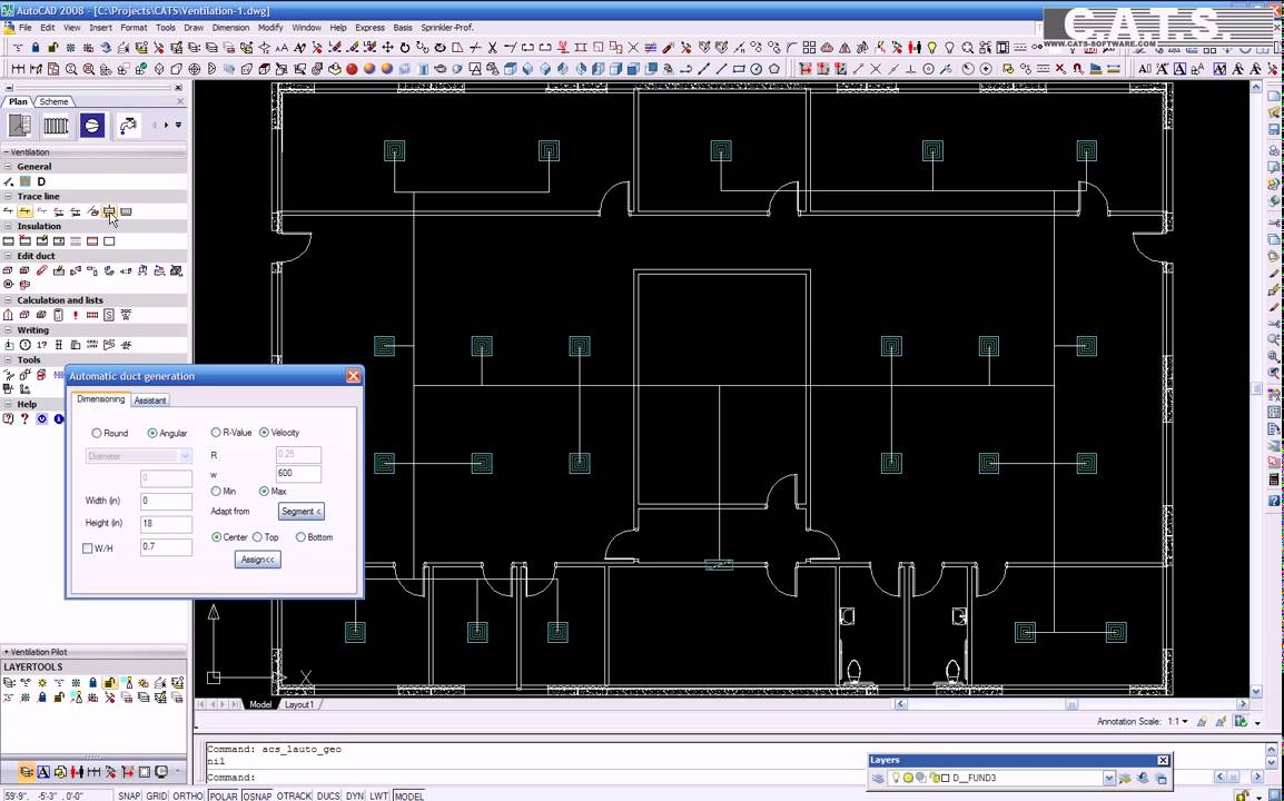
By clicking on walls or entering a surface, the optimum sprinklers are automatically positioned in the plan in accordance with the VdS rules and NFPA standards, after selecting the sprinkler types, parameters, protection zones and heights.
Alternatively, the sprinklers can also be positioned in terms of reference points and edited with all standard AutoCAD functions, such as Copy, Move, etc.
In addition to the sprinkler types in the available database, it is also possible to create individually configured sprinklers.
Technical data and symbols are immediately provided for this purpose. The main and branch pipelines are added either individually or in groups. Existing AutoCAD lines can be transformed into intelligent pipelines.
Additionally a large library with valves, components and pumps is available. For the complete pipeline network there are numerous test routines which check and then automatically correct any errors.
For calculations two methods are available which also allow for the calculation of foaming agents.
After the sprinklers and pipelines have been automatically numbered, the corresponding effective surfaces are created.
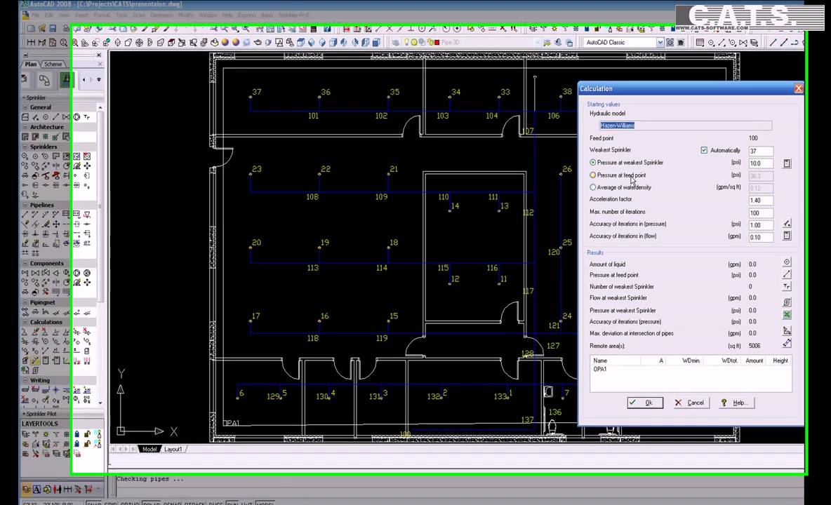
Once the direction of flow has been determined, the calculation can begin. The calculation is performed in accordance with the pressure at the least effective sprinkler, the feed point or in terms of the average water impingement.
All results are clearly laid out and displayed immediately. All changes of the pipelines are associative and immediately realized in the drawing. Output is in VdS format, either as Ascii or directly in Excel.
Finally, the system components are extracted; the lists can be configured freely as required so that they give the user the required information. The module-universal collision test helps the user in coordinating the individual modules.
Calculations
With approval of the society of non-life insurances
Calculation method as per Hazen-Williams, or Darcy-Weisbach and NFPA
Calculation of e.g. foaming agents
Editable database for all components
Tabular inputting of sprinklers, components and pipelines
Automatic reading of all data from the drawing, such as elbows, branches etc.
Choice of calculation in terms of pressure at least effective sprinkler, feed point, or water impingement
Reports as per VdS format available in Ascii or Excel.
Masses
Automatic reading of all data from the drawing, such as bends, branches, etc.
Outputting of sprinklers, pipelines, fittings, valves, etc.
Incorporation of parts list in the drawing, alternative output in Excel, PDF etc.
Overview of functions
CAD
Generation of drawing, assembly and as-built drawings
Automatic generation of isometric and section views
2D library with access to more than 100 graphical symbols
2D recesses for slits and openings
Flexible management of added storey plans
Editable databases for all components, including transfer of defined symbols
Automatic placement of sprinklers in accordance with VdS rules
Pipelines displayed as single lines, in analogy with AutoCAD Line command
Fully automatic generation of branch lines
Optional conversion of lines, circles, etc. to sprinkler objects
Editing functions for individual components or for complete pipe system
Generation of angle branch-offs and automatic pipe branch connections
Checking and correction functions for each section of the construction
Associative dimensioning, for instance with pipelines, flow speed, information signs, etc.
Automatic display of risers, mountings, flow directions, etc.
Associative indicators, definable pipe and spatial references
Automatic numbering of components and pipes
Construction of effective area with automatic area statement
Deduction of flow direction in preparation for calculation
Automatic construction of pump characteristic lines in the drawing
Price summary made by simple assignment of attributes
Spatial display in 3D and collision test, optional following calculation
Повторяем попытку...

Доступные форматы для скачивания:
Скачать видео
-
Информация по загрузке:
![Best of Deep House [2026] | Melodic House & Progressive Flow](https://imager.clipsaver.ru/Il-ZpBuC8tA/max.jpg)