workflow AutoCAD -Autodesk Structural Bridge design applied to a BOX GIRDER Bridge
Автор: BIM DRCONGO
Загружено: 2021-11-03
Просмотров: 4603
Описание:
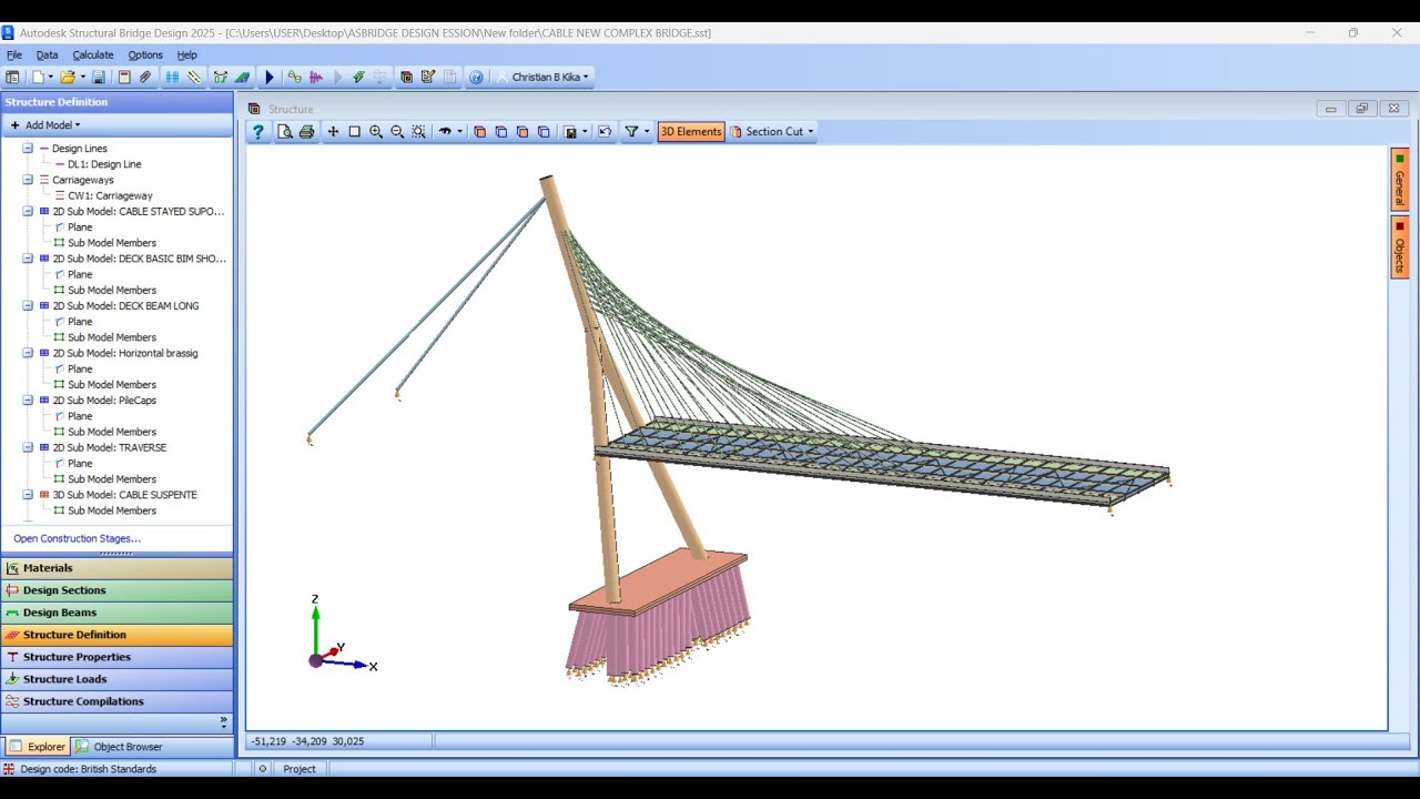
The box girder bridge below has a slab thickness of 200mm and a bottom flange thickness of 275mm. The thickness of the webs is 250mm. The structure is modelled using 3D shell finite elements. The geometry of the structure is complicated with the slab (curved on plan) and sloping webs of the box girders. A structure with such geometry would be difficult to define directly in Autodesk Structural Bridge Design. However, such geometry is relatively easy to define in AutoCAD. Hence, a DXF file has been prepared in AutoCAD using a set of specialised commands which are loaded into AutoCAD. The DXF file will be imported into Autodesk Structural Bridge Design to define the geometry of the structure.
Below is the drawing file containing the geometric data for the finite elements. Note
that Autodesk Structural Bridge Design will recognise only elements defined using
either the specialised commands, or individually drawn 3D FACE entities, as finite
elements when data from the DXF file is imported into Autodesk Structural Bridge
Design.
facebook page
/ laesgcsarl
Повторяем попытку...

Доступные форматы для скачивания:
Скачать видео
-
Информация по загрузке: