NAND Gate Using Transistors
Автор: Shantha c Mukartihal
Загружено: 2025-03-19
Просмотров: 105
Описание:
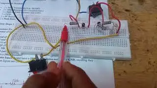
Transistor Configuration
1.Q1 and Q2 are NPN transistors (BC547 or 2N3904).
2.Base resistors (R1, R2 - 10kΩ) limit base current for proper transistor operation.
3.Pull-up resistor (R3 - 330Ω) ensures the output node is HIGH when transistors are OFF.
4.The LED is correctly placed between the output node and GND.
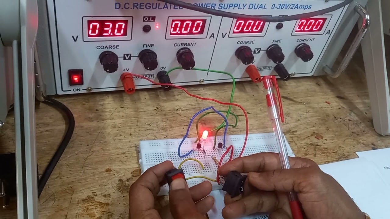
Operation Based on Inputs A & B:
1.Case 1: A = 0, B = 0 (Both switches open)
1.No base current → Both transistors OFF.
2.Collector node (Y) stays HIGH (5V) (due to pull-up resistor R3).
3.LED turns ON (5V across LED).
2.Case 2: A = 0, B = 1 (One switch open, one closed)
1.Q1 OFF, Q2 ON → Collector node still HIGH (5V).
2.LED stays ON.
3.Case 3: A = 1, B = 0 (One switch open, one closed)
1.Q1 ON, Q2 OFF → Collector node remains HIGH (5V).
2.LED stays ON.
4.Case 4: A = 1, B = 1 (Both switches closed)
1.Both transistors turn ON → Collector node pulled LOW (0V).
2.LED turns OFF.
Повторяем попытку...
Доступные форматы для скачивания:
Скачать видео
-
Информация по загрузке: