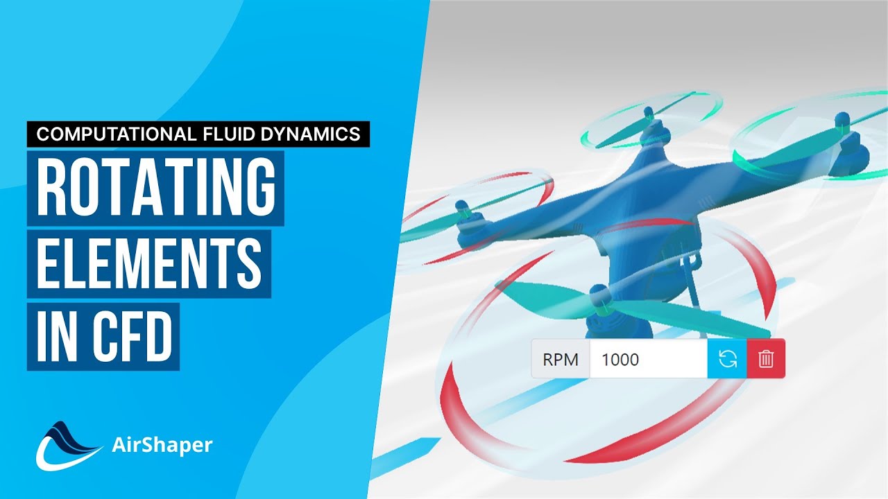
How to model Rotating Elements in CFD (computational fluid dynamics) using MRF, AMI and more
Автор: AirShaper
Загружено: 2022-01-12
Просмотров: 7319
Описание:
To learn more about CFD simulations: • Computational Fluid Dynamics Explained
Rotating Wall Boundary Condition
The simplest form is the rotating wall boundary condition. Without rotation, the velocity of the airflow is always zero at the surface because of the no slip condition. The rotating wall boundary condition simply enforces a tangential velocity onto the surface of the rotating object. This velocity is equal to the distance from the center multiplied by the rotational velocity. The further you move away from the center, the higher the velocity.
This technique is very simple and doesn’t significantly change the cost of computation, as no extra equations are introduced and the flow can be solved in a steady state manner. It’s very suitable on surfaces that are tangential to the local direction of rotation.
At AirShaper, we chose this technique to take the rotating wheels of cars into account, as it’s a very robust solution. When you click a tire, the axis of rotation will be detected automatically, the components inside will be selected as well and the rotational velocity is automatically linked to the driving speed of the vehicle
MRF – Multiple Reference Frame
For more complex geometries with a lot of non-tangential surfaces, the more advanced MRF technique can be used. It stands for multiple reference frames. In essence, you create a separate region around the rotating object. Inside this region, for each point, you calculate the relative velocity, which is a combination of the absolute velocity and the rotational velocity.
The Navier-Stokes flow equations are then built on top of this relative velocity, which results in extra terms that take the Coriolis and centrifugal forces into account. So, you end up with a set of equations for the stationary region and another set for the rotating region.
This method is a bit more expensive in terms of computational cost, but still allows for steady-state calculations and it’s able to accurately capture the “instantaneous” flow pattern around a propeller for example.
At AirShaper, we chose to use this technique when adding rotating propellers to a simulation. When selecting a propeller, the central axis will automatically be detected. The direction of rotation can be flipped and the RPM can be set by the user. And it is possible to add multiple propellers to a single simulation
AMI – Arbitrary Mesh Interface
This instantaneous flow, however, can depend heavily on the relative position of the rotating part versus the static part, like a propeller versus a strut. So, for very advanced simulations, there’s also the AMI technique, which stands for arbitrary mesh interface. In this technique, the mesh around the rotating object is actually cut and then made to rotate. This can only be done using transient simulations, as the rotation of the mesh is now linked to the actual time step. At the sliding mesh interface, the cells of the stationary and rotating mesh exchange information on the flow.
This technique is usually the most accurate, but also very demanding in terms of computational effort. It can also be challenging in terms of stability, as the mesh interface needs to be defined very well. This type of simulation usually requires a manual approach.
-----------------------------------------------------------------------------------------------------------
The AirShaper videos cover the basics of aerodynamics (aerodynamic drag, drag & lift coefficients, boundary layer theory, flow separation, reynolds number...), simulation aspects (computational fluid dynamics, CFD meshing, ...) and aerodynamic testing (wind tunnel testing, flow visualization, ...).
We then use those basics to explain the aerodynamics of (race) cars (aerodynamic efficiency of electric vehicles, aerodynamic drag, downforce, aero maps, formula one aerodynamics, ...), drones and airplanes (propellers, airfoils, electric aviation, eVTOLS, ...), motorcycles (wind buffeting, motogp aerodynamics, ...) and more!
For more information, visit www.airshaper.com
Повторяем попытку...
Доступные форматы для скачивания:
Скачать видео
-
Информация по загрузке:
![[CFD] Multiple Reference Frame (MRF) Approach for Turbomachinery](https://imager.clipsaver.ru/oa-xcE0_0UY/max.jpg)

![[CFD] Porous Zones in CFD](https://imager.clipsaver.ru/sOQMXxoKFQM/max.jpg)


![[CFD] How Fine should my CFD mesh be?](https://imager.clipsaver.ru/60fDz2cVdy8/max.jpg)


![[CFD] What is the difference between y+ and y*?](https://imager.clipsaver.ru/nSdVaF3JnI0/max.jpg)