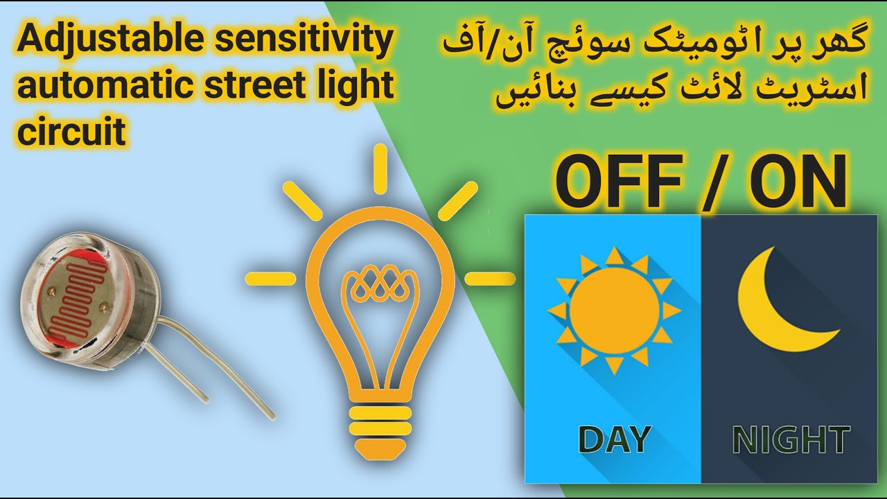
Adjustable sensitivity automatic street light circuit 1080p گھر پر اٹومیٹک سوئچ آن/آف اسٹریٹ لائٹ
Автор: Qudrat official
Загружено: 2023-03-14
Просмотров: 26
Описание:
Your Queries:-
how an adjustable sensitivity automatic street light circuit can work.
The basic idea behind an adjustable sensitivity automatic street light circuit is to use a light sensor to detect the ambient light levels, and then turn on or off the street lights based on the detected levels. By adjusting the sensitivity of the light sensor, you can control the threshold level at which the lights turn on or off.
To build such a circuit, you will need the following components:
Light sensor (LDR - Light Dependent Resistor)
555 timer IC
Transistor (NPN)
Resistor
Capacitor
Diode
Relay
Power supply
The circuit works as follows:
1. When the ambient light levels are low, the LDR's resistance increases and the voltage across it decreases. This lower voltage triggers the 555 timer IC's output to go high.
2. The high output from the 555 timer IC switches on the NPN transistor, which in turn charges the capacitor.
3. As the capacitor charges, its voltage increases until it reaches the threshold level set by the adjustable resistor. At this point, the output of the 555 timer IC goes low, which switches off the NPN transistor and the capacitor begins discharging.
4. When the capacitor's voltage falls below a certain level, the output from the 555 timer IC goes high again, and the cycle repeats.
5. The output from the 555 timer IC is connected to a relay that switches the street lights on or off depending on the state of the output.
By adjusting the value of the resistor in the circuit, you can change the sensitivity of the LDR, and hence the light levels at which the street lights turn on or off.
steps for creating an adjustable sensitivity automatic street light circuit:
Materials needed:
Light sensor (LDR)
Transistor (BC547)
Resistor (2.2 KΩ)
Resistor (470 Ω)
Potentiometer (100 KΩ)
LED
Relay module
Power source (12V DC)
Steps:
1. Connect the LDR between the base of the transistor and ground.
2. Attach the 2.2 KΩ resistor between the base of the transistor and the potentiometer.
3. Connect the potentiometer between the 2.2 KΩ resistor and the positive terminal of the power source.
4. Connect the 470 Ω resistor between the collector of the transistor and the positive terminal of the power source.
5. Connect the LED between the collector of the transistor and ground.
6. Connect the relay module to the collector and emitter of the transistor.
7. Connect the power source to the relay module.
Adjusting the sensitivity:
Adjust the potentiometer to adjust the sensitivity of the circuit.
When the light intensity falls below a certain level, the LDR resistance increases and the current flows through the transistor, turning on the LED and switching on the relay, which then activates the street light.
Note: It is advised to do this project under the supervision of an experienced electronic hobbyist.
#habibofficial44224
#discovrycomedy2257
#youtube
#qudratofficial7788
Повторяем попытку...
Доступные форматы для скачивания:
Скачать видео
-
Информация по загрузке: