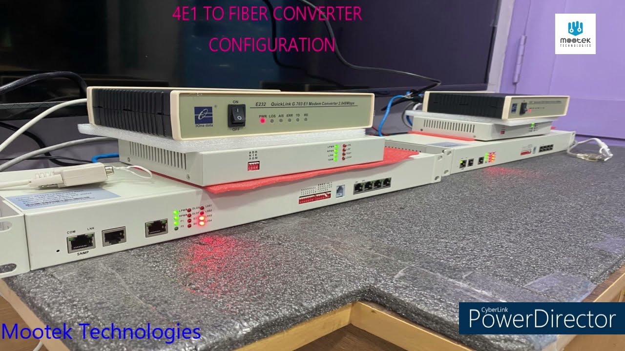
How to Configure 4E1 to Fiber Converter
Автор: Mootek Technologies
Загружено: 2021-09-03
Просмотров: 1585
Описание:
E1 to Fiber Converter Configuration Method:
-----------------------------------------------------------------------
How to Configure 4E1 to Fiber Input: E1 , Total 4 Inputs Output: Fiber
Before using the device read the user manual , LED position ,Pin details E1 side and Fiber side,
Step:1
Open 4E1 to Fiber device from Box and Power on. Check all LED Status and keep mind it. Need pair to use this device 1 - Local Device/Control Room/ 2- Remote Location
Step:2
Connect Fiber Line first Regarding the Fiber Line, It has SFP Slots, So you have to add SFP module in that slot. SFP Module based on your requirements Mode ? Single mode or Multi Mode ? Connector ? LC Type Range: 20Km
Step:3
Local Device and Remote Location once connected fiber line check the LED Status. It should be Power On, Then its in Position to transfer the datas Based on Manufacturer LED position assigned, so check LED before connecting Fiber line and after connection too.
Step:4
E1- Input You can Connect any E1 Input, but it should be E1 Protocol signals. I have Ethernet to E1 device, through this I am going to give E1 signals to 4E1 device.
Step:5
INPUT 1 , E1 signals. Power On devices, and Watch LED Position now. Through this I am going to transfer internet datas, Ethernet Connected to E1 Device, E1 device Output Connected to 4E1 input 1 Here pin details are very important EX: E1 Input Side 4E1 side ,1st Inputr Side ============. =============== PIN 1 (Tx+) ——— ——— PIN 4(Rx+) PIN 2 (Tx-)——— ——— PIN 5(Rx-)
PIN 4 (Rx+) —— ———— PIN1(Tx+) PIN5 (Rx-)——— ———— PIN2(Tx-) Local Location and remote Location Both are connect Like this.
Step:6
Check LED Status LOS Should be Power OFF, before connecting its Power on, After connection if the E1 Signal is proper then it will be OFF Position.
Step:6 E1 Side INPUT Signal 2 Here I am going to use SERIAL to E1 device, These E1 signal I am going to give 4E1 side 2nd input.
See this is another manufacturer E1 signal device , so Pin details are different Example: E1 Input Side 4E1 side ,2st Input Side ============. =============== PIN 6 (Tx+) ——— ——— PIN 4(Rx+) PIN 7 (Tx-)——— ——— PIN 5(Rx-) PIN 2 (Rx+) —— ———— PIN1(Tx+) PIN 3 (Rx-)——— ———— PIN2(Tx-) Local Location and remote Location Both are connect Like this in 4E1 side 2nd E1 INPUT
Step:7
Check LED status from both side. LED Status: LOS2- blinking , When data transferring properly it will be OFF, data flowing but if you not able to view the LED will blink, Like this, Please Watch the Position.
Повторяем попытку...
Доступные форматы для скачивания:
Скачать видео
-
Информация по загрузке: