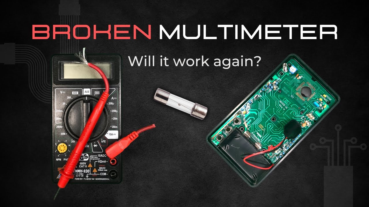
Fixing a broken Multimeter - will it work again?
Автор: No Expert
Загружено: 2023-03-04
Просмотров: 2500
Описание:
#noexpert #diyprojects #repairing #multimeter
In this video we are taking a look at a broken multimeter and I see if I can fix it. It’s nothing fancy and I could just throw it away, but I really like to make use of things that can be repaired. After all, the constant production of new things is not only a big driver of the economy, but also of the pollution that has a bad influence on our planet. If more things could and would be repaired, that would be a step into the right direction so at least I’d like to try.
#1 Obvious Problems
The fuse is popped and one of the terminals is rotting away, so in preparation for this repair I bought some new parts. I got two shiny new fuses in case I break one and a battery clip for 9 volt block batteries. I put one fuse into its place and start to unscrew the PCB so I can access the connections. It is a bit tricky but with some gentle levering I can pop it out.
#2 (De)soldering
I was hoping that the ends of the battery clip is still intact so I can solder the new one directly to the wires instead of the PCB. Unfortunately they have come lose and I need to remove the remains first.
One gentle touch is enough to take the first wire out, the second one is a bit more tricky. I lost my patience with the old solder that just wouldn’t liquify and drilled into it, burning the PCB. Hope it still works. The new wires slide in like a charm and with some fresh solder it seems like they make a good connection even on the burnt PCB.
#3 Reassembly
I test for continuity using a little scratch on the outside conductor of the circuit - and it works. The other one leads to the inside of the selector circle, which also works. So at least I didn’t fry the PCB which is good.
In order to actually test it, I need to put everything back together. In the video you see little copper bridges which tend to fly off as soon as you remove the dial. They are like mechanical switches to select the right circuit for your measurement, without them the multimeter won’t work. The same goes for the little bearing balls which are spring loaded.
When I looked into my other multimeter I had one of these balls fly across the room and it took me half an hour to find it. They are responsible for the clickyness of the selector (dial) and you can’t just leave them out because the whole system relies on the two balls being in the perfect position.
#4 Testing & Takeaway
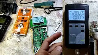
Once everything was back together, it turned on for a second and then died again, even though the battery was new. It took ages until I tried using another battery and then it worked. It doesn’t make sense because both had the same voltage (I tested both) but that’s old electronics I guess. I then hoked it up to my lab power supply to see what the multimeter detects. The measurement is off all the time and not by a constant, it keeps changing.
With that amount of fluctuating error it’s pretty much useless but hey, it was still nice to take a look into it and worth a try. My main takeaway is that not all projects turn out the way you want but thats okay as long as you learn something or at least have some fun.
If you know how I can fix that offset and recalibrate it, please leave a comment below.
Until next time
NoExpert
Here are some Timestamps:
00:00 Intro
00:23 Obvious Problems
01:09 New Parts Arrived
01:30 Disassembly
02:20 New Battery Terminal
02:45 Testing Continuity
03:21 Reassembly
04:13 Test 1
04:28 Test 2
04:43 Test 3 with Lab Supply
Повторяем попытку...
Доступные форматы для скачивания:
Скачать видео
-
Информация по загрузке: