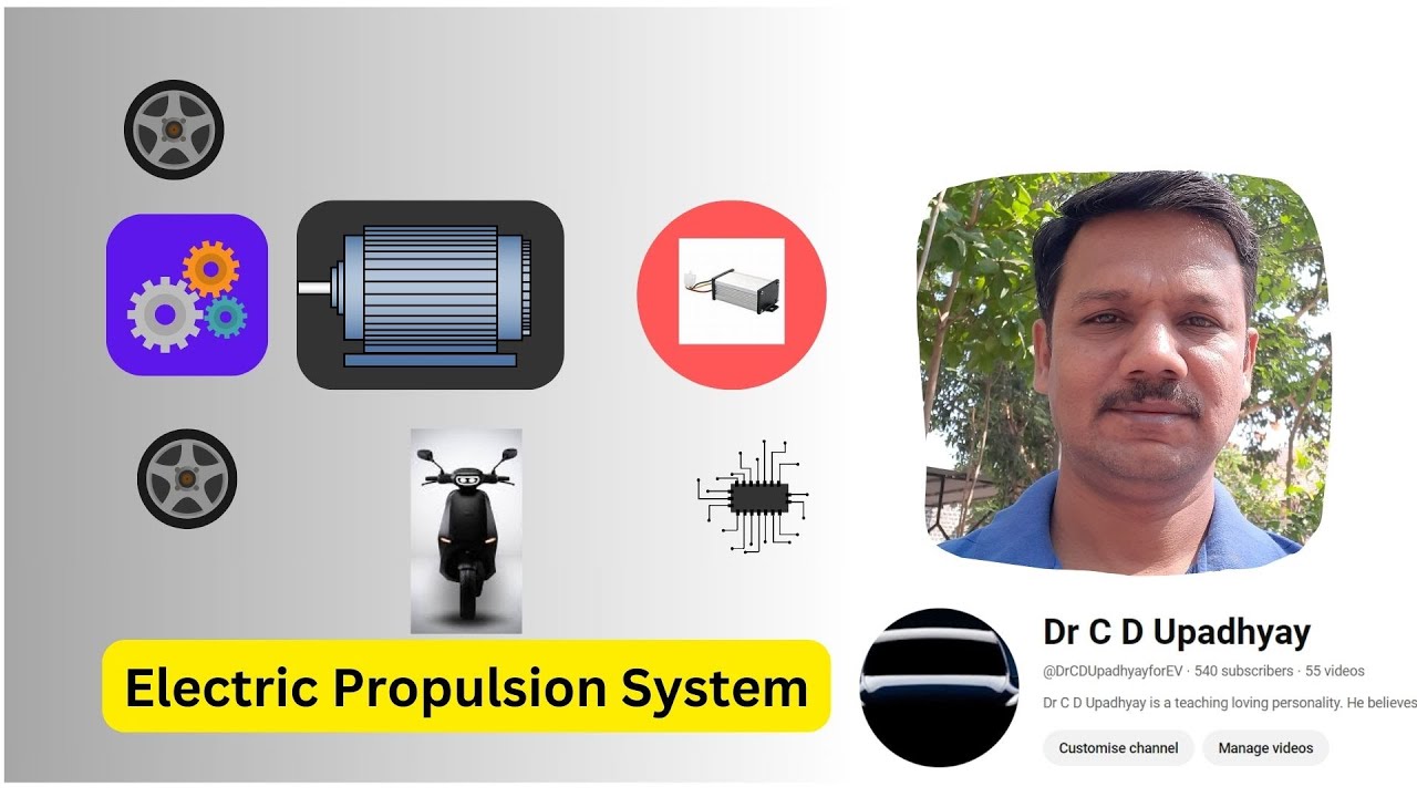
Functional Block diagram of EPS (Electric Propulsion System)
Автор: Dr C D Upadhyay
Загружено: 2023-10-05
Просмотров: 645
Описание:
Electric propulsion systems are at the heart of electric vehicles (EVs) and hybrid electric vehicles (HEVs). They consist of electric motors, power converters, and electronic controllers. The electric motor converts the electric energy into mechanical energy to propel the vehicle, or, vice versa, to enable regenerative braking and/or to generate electricity for the purpose of charging the onboard energy storage. The power converter is used to supply the electric motor with proper voltage and current. The electronic controller
commands the power converter by providing control signals to it, and then
controls the operation of the electric motor to produce proper torque and
speed, according to the command from the drive. The electronic controller
can be further divided into three functional units — sensor, interface circuitry, and processor. The sensor is used to translate measurable quantities such as current, voltage, temperature, speed, torque, and flux into electric signals through the interface circuitry. These signals are conditioned to the appropriate level before being fed into the processor. The processor output
signals are usually amplified via the interface circuitry to drive power semiconductor devices of the power converter. The functional block diagram of an electric propulsion system is discussed here.
Повторяем попытку...
Доступные форматы для скачивания:
Скачать видео
-
Информация по загрузке: