DDC Connection Overview Relay NO/NC & Communication Indication Explained? DDC Connection Kya Hai?
Автор: Control Room Live #Vlog.
Загружено: 2025-12-12
Просмотров: 60
Описание:
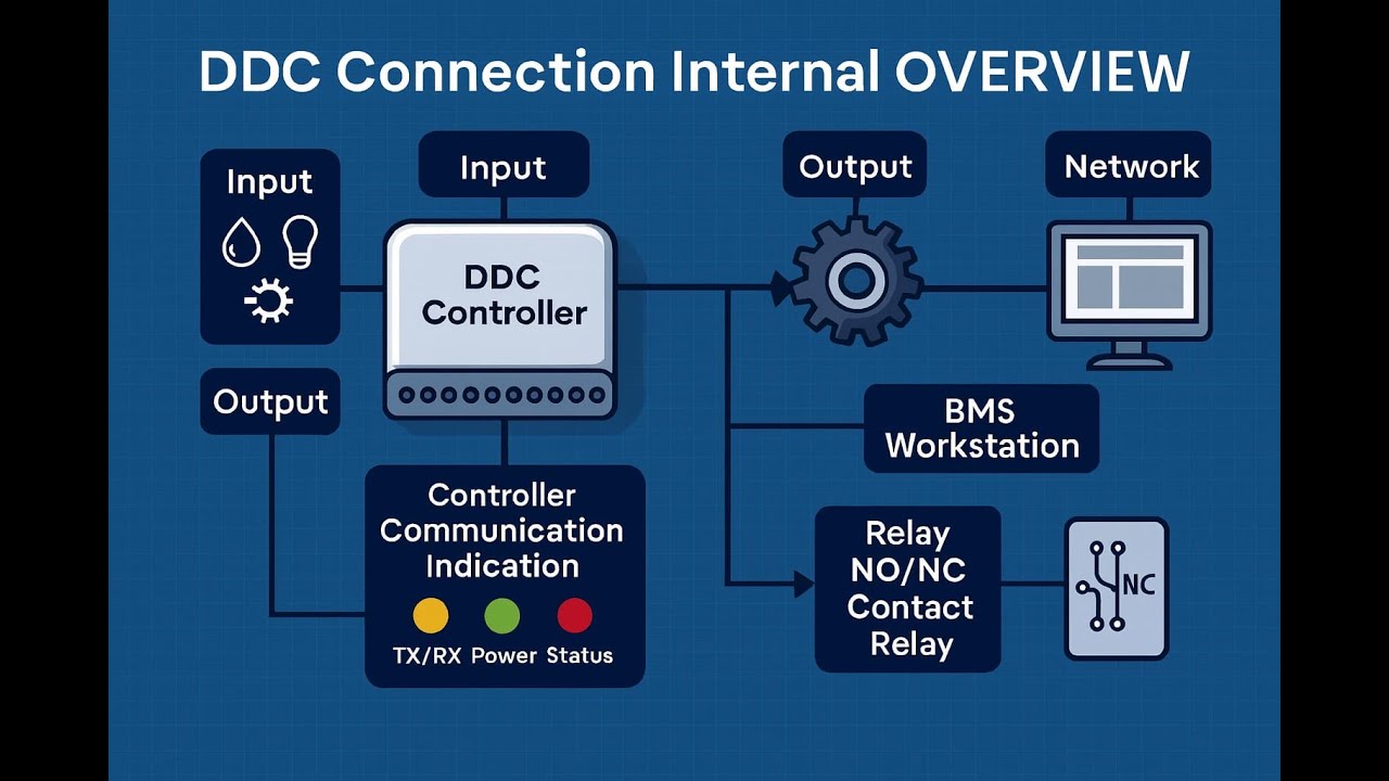
DDC Connection Internal Overview
1. Core Components
• DDC Controllers
o Microprocessor-based units that process inputs and generate outputs.
o Store control logic, schedules, and setpoints.
o Communicate with supervisory systems (like BMS servers).
• Sensors (Inputs)
o Measure variables: temperature, humidity, pressure, flow, occupancy.
o Provide analog (e.g., 0–10 V, 4–20 mA) or digital (on/off) signals.
• Actuators (Outputs)
• Control devices: valves, dampers, fans, pumps.
• Receive signals from the controller to adjust HVAC equipment.
2. Types of Connections
• Analog Inputs (AI)
o Continuous signals (temperature probe, pressure transducer).
o Example: 0–10 VDC or 4–20 mA loop.
• Digital Inputs (DI)
o Binary signals (switches, alarms, status feedback).
o Example: Fan status ON/OFF.
• Analog Outputs (AO)
o Continuous control signals to modulate actuators.
o Example: 0–10 VDC to control damper position.
• Digital Outputs (DO)
• Binary commands to start/stop equipment.
• Example: Relay output to energize a pump.
3. Internal Communication
• Controller Bus
o Internal wiring between controller modules (I/O expansion boards).
o Ensures scalability for large systems.
• Field Bus (Network Layer)
o Protocols like BACnet, Modbus, LonWorks.
o Connects multiple controllers to the BMS server.
o Provides interoperability between different vendors.
• Power Supply
• Controllers and field devices require stable DC power (often 24V).
• Isolation and grounding are critical to avoid signal noise.
4. Signal Flow Example
1. Sensor detects room temperature (AI).
2. Controller processes input against setpoint logic.
3. Controller outputs signal (AO) to modulate valve actuator.
4. Actuator adjusts chilled water flow.
5. Feedback signal (DI) confirms valve position/status.
6. Controller reports data to BMS workstation via BACnet.
5. Best Practices
• Proper shielding and grounding for analog signals to reduce interference.
• Use separate power supplies for controllers and field devices when required.
• Maintain consistent addressing in BACnet/Modbus networks.
• Document all connections in as-built drawings for troubleshooting.
This overview gives you the internal wiring and communication picture of DDC systems — essentially how inputs, outputs, controllers, and networks tie together to make HVAC automation possible.
DDC Connection Internal Overview with Relay NO/NC Contacts
1. Role of Relays in DDC
• Isolation: Protects the DDC controller from high voltage/current loads.
• Switching: Allows low power controller outputs to operate larger equipment (fans, pumps, compressors).
• Flexibility: Provides both NO and NC contacts for different control strategies.
2. Relay Contact Types
• NO (Normally Open):
o Circuit is open when relay coil is de energized.
o Closes when coil is energized → allows current flow.
o Commonly used for start/enable commands (e.g., fan ON when controller energizes relay).
• NC (Normally Closed):
• Circuit is closed when relay coil is de energized.
• Opens when coil is energized → stops current flow.
• Commonly used for fail safe or shutdown circuits (e.g., equipment OFF if controller loses power).
3. Typical DDC Relay Wiring
• Controller DO (Digital Output): Sends signal to energize relay coil (often 24VDC).
• Relay Coil: Energized by DO, changes contact state.
• Relay Contacts (NO/NC): Connected to field device power/control circuit.
• Field Device: Receives ON/OFF control depending on relay contact state.
4. Signal Flow Example
1. Controller DO energizes relay coil.
2. Relay NO contact closes → completes circuit to fan motor starter → fan runs.
3. If controller DO de energizes:
• Relay NO opens → fan stops.
• Relay NC closes → could send feedback signal (e.g., “fan off” status).
5. Integration with Inputs
• Status Feedback (DI):
o Relay auxiliary contacts can be wired back to controller DI.
o Confirms whether equipment actually started/stopped.
• Safety Interlocks:
• NC contacts often used in safety chains (e.g., fire alarm trip, overload protection).
6. Best Practices
• Always label NO/NC contacts in wiring diagrams.
• Use fail safe design: critical equipment should default to safe state if relay fails.
• Ensure separation of control voltage and power circuits.
• Document relay logic in as built schematics for troubleshooting.
🔧 Simplified Diagram (Textual)
Controller DO (24VDC) → Relay Coil Relay NO → Fan Motor Starter (ON when coil energized) Relay NC → Safety/Feedback Circuit (ON when coil de-energized)
This setup is fundamental in BMS engineering interviews: showing you understand how DDC controllers interface with real world equipment using relay NO/NC contacts demonstrates both theory and practical knowledge.
📲 Chat with us on WhatsApp for queries or collaboration:
+966 569190065
+966 553649063.
Follow this link to join my WhatsApp group: https://chat.whatsapp.com/BPhhkGfOuFc...
Повторяем попытку...
Доступные форматы для скачивания:
Скачать видео
-
Информация по загрузке:


