[FluidSIM] Mechatronics - Electro Pneumatic Circuit of A+B+A-B-[ Explained]
Автор: Gaurav Mungekar
Загружено: 2017-06-06
Просмотров: 30916
Описание:
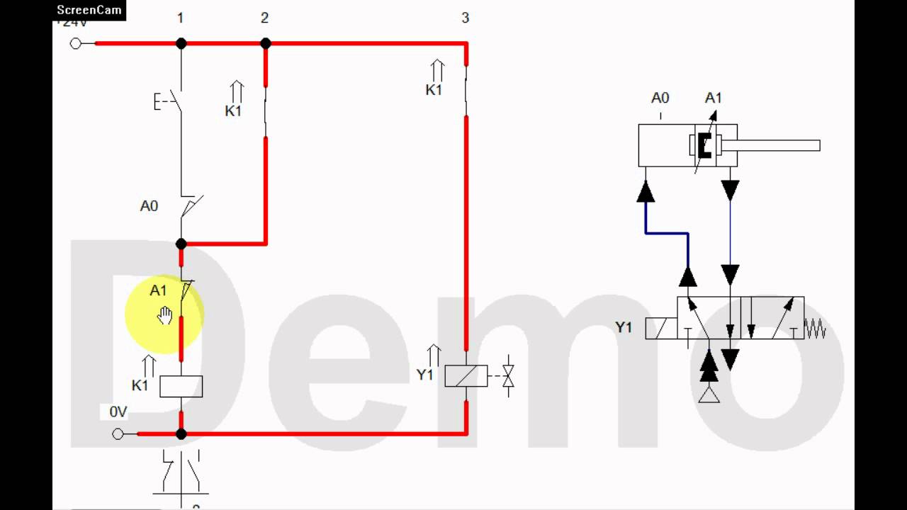
This video explains how to draw Electro-Pneumatic Circuit of A+B+A-B- sequence [MU Mechatronics]
Steps to draw Pneumatic part of Electro-Pneumatic Circuit:
1. Cylinders - Draw cylinders as per final position of sequence and name each cylinder.
2. Limit Swiches - Give names to limit switches
3. DCV - Draw direction control valves (Mostly double solenoid operated) and its position depend on final position of cylinder
4. Draw compressor and exhaust. Draw pressure lines.
Steps to draw Electricc part of Electro-Pneumatic Circuit:
1. Decide Number of relays required
2. Draw Power supply lines of +24V and 0V
3. Draw Push button (single cycle) and detent switch (multi cycle)
4. Draw roller operated normally closed limit switch of last actuated position of cylinder
5. Draw relay 1
6. Draw memory unit
7. Draw all operation corresponding to relay 1 (if one operation has to done after another, then draw roller operated normally open limit switch)
8. Draw second roller operated normally open limit switch
9. Draw relay 2
10. Draw memory unit
11. Draw all operation corresponding to relay 2 (if one operation has to done after another, then draw roller operated normally open limit switch)
Visit My Channel to see more - / @gaurav_mungekar
Software Used - FluidSIM
Intro Channel - / @anti-light (FreeMyMusic)
Intro - • Видео (Free Intro Music 10 Seconds (EDM) - FreeMyMusic)
Повторяем попытку...
![[FluidSIM] Mechatronics - Electro Pneumatic Circuit of A+B+A-B-[ Explained]](https://imager.clipsaver.ru/faow2qJ0YdU/max.jpg)
Доступные форматы для скачивания:
Скачать видео
-
Информация по загрузке:

![[FluidSIM] Mechatronics - How to make Pneumatic Circuit of A+B+A-B-](https://imager.clipsaver.ru/3-Uvr3F7jUs/max.jpg)


![Secuencia 1: A+ A- B+ B- [Método Paso a Paso]](https://imager.clipsaver.ru/S7vmsX_8DNE/max.jpg)