NAND Gate Using Diodes
Автор: Electro Spark
Загружено: 2026-01-28
Просмотров: 8
Описание:
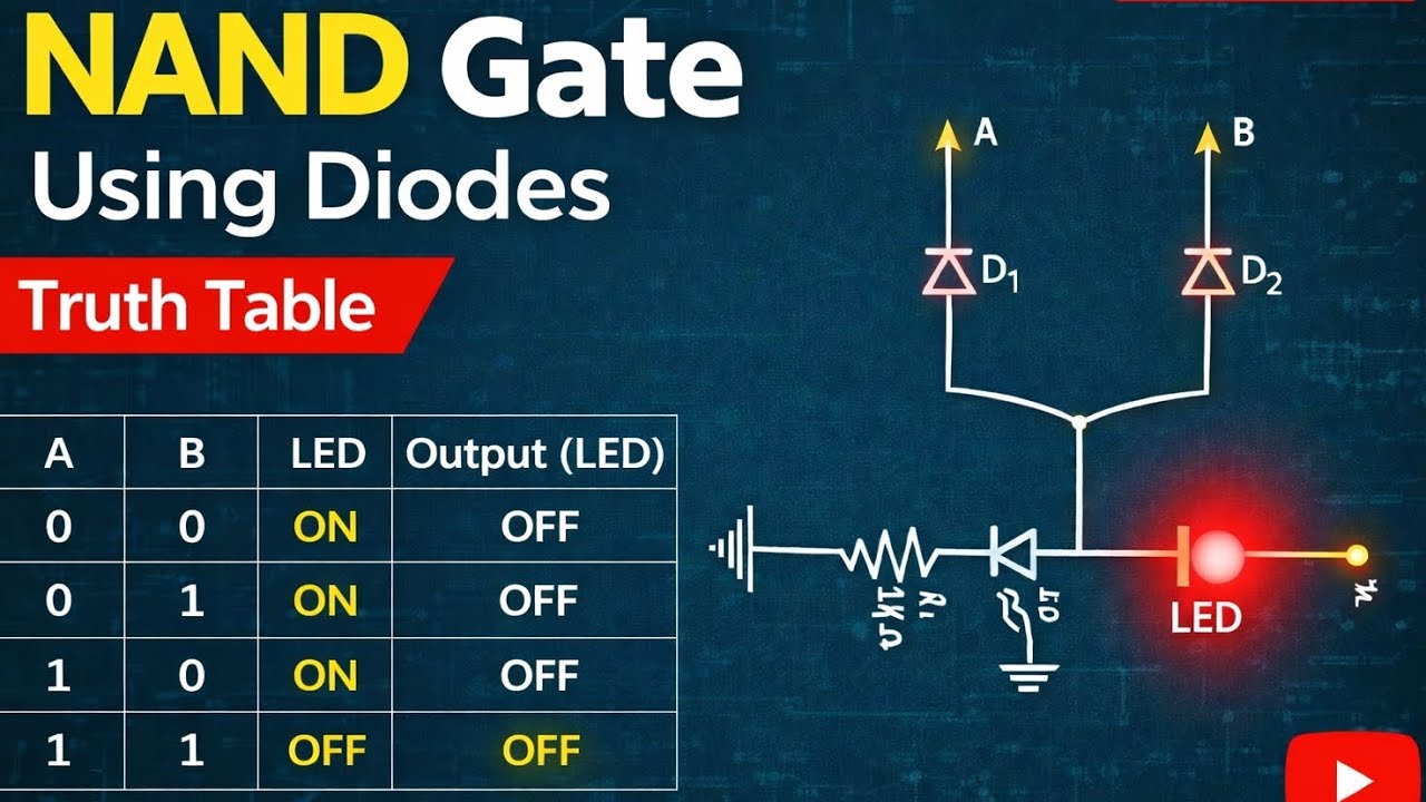
NAND Gate Using Diodes | Digital Logic Circuit with Truth Table
In this video, I demonstrate the working of a NAND gate implemented using diodes, a resistor, and an LED, without using any logic IC. This project helps in understanding the basic concept of universal logic gates through simple hardware implementation.
A NAND gate is the inverse of an AND gate, meaning the output becomes LOW only when both inputs are HIGH. The output state is visually indicated using an LED.
Circuit Overview:
Logic inputs: A and B
Components used: Diodes, resistor (1 kΩ), LED
Output indication: LED ON / OFF
Implementation: Discrete components (no IC)
Working Principle:
When A = 0 or B = 0, the output remains HIGH (LED ON)
When A = 1 and B = 1, the output becomes LOW (LED OFF)
The circuit behavior follows the NAND gate truth table
Truth Table:
A
B
Output (LED)
0
0
ON
0
1
ON
1
0
ON
1
1
OFF
Why NAND Gate?
NAND gate is a universal gate
Any logic circuit can be implemented using only NAND gates
Widely used in digital systems and processors
This video is useful for:
Digital Electronics beginners
Engineering and diploma students
Understanding logic gates using hardware circuits
Academic lab experiments and mini-projects
📌 Like, Share, and Subscribe for more digital electronics and logic gate projects.
Повторяем попытку...
Доступные форматы для скачивания:
Скачать видео
-
Информация по загрузке:

![GOSPODARKA WOJENNA ROSJI - CZY PUTIN JUŻ PRODUKUJE CZOŁGI ZAMIAST LODÓWEK [BOJKE]](https://image.4k-video.ru/id-video/g2t5npoRfBA)