SIMPLE TRAFFIC LIGHT SYSTEM SIMULATION USING PLC
Автор: Divyam Gupta
Загружено: 2026-01-05
Просмотров: 1
Описание:
DIVYAM GUPTA (UE239024) 5th SEMESTER
MECHANICAL SECTION - 1 GROUP - 1
UIET, PANJAB UNIVERSITY, CHANDIGARH
METHODOLOGY
1. In the first step we add 4 buttons
a. START
b. GREEN
c. YELLOW
d. RED
2. In the next step we add 3 timers
a. GREEN TIMER
b. RED TIMER
c. YELLOW TIMER
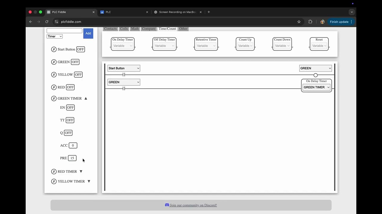
3. Then we add RUNG (horizontal) and add contact variable for input and coil for output,
In this step START button in assigned as the Input and GREEN button as the output
4. As we are working in series for the traffic light the previous output becomes the input, So in the next rung we add contact variable = GREEN button and an ON DELAY TIMER = GREEN TIMER. We have used an ON DELAY TIMER to introduce a fixed time delay before changing from one signal to the next.
5. In the next rung we again add contact variable = GREEN TIMER.Q (We use TIMER.Q because it becomes TRUE only after the preset time has fully elapsed) and YELLOW button as the output.
6. We repeat the same for yellow and red in the following rungs
next rung : input = YELLOW button output = ON DELAY TIMER with value = YELLOW TIMER
next rung : input = YELLOW TIMER.Q output = RED button
7. For RED LIGHT
next rung : input = RED button output = ON DELAY TIMER with value = RED TIMER
8. To run this in LOOP, We add one more rung
next rung : input = RED TIMER.Q output = GREEN BUTTON
THINGS TO KEEP IN MIND
Uses ON-Delay (TON) → ensures fixed signal time
Uses Timer.Q → ensures safe and complete timing
Previous output used as next input → series sequencing
Prevents overlap of signals
Повторяем попытку...
Доступные форматы для скачивания:
Скачать видео
-
Информация по загрузке:


