BJT Common-Emitter Amplifier 🎯 Midband Gain, Low-Frequency & High-Frequency Cutoff 👉 FULL DETAILS💡
Автор: CAN Education
Загружено: 2025-05-28
Просмотров: 1738
Описание:
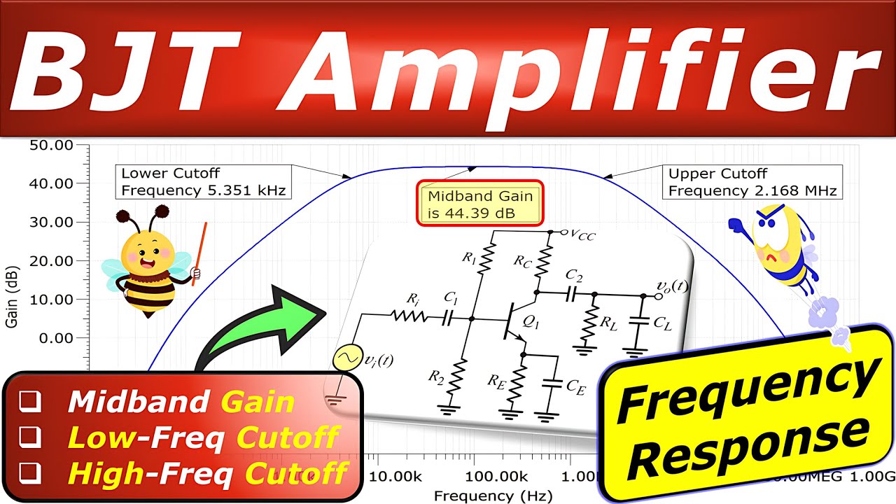
In this video, we take a detailed look at the frequency response analysis of a BJT Common-Emitter Amplifier using an NPN transistor. The circuit includes four capacitors:
🔹Input coupling capacitor (C1)
🔹Output coupling capacitor (C2)
🔹Emitter bypass capacitor (CE)
🔹Load capacitor (CL)
💡 To structure the discussion clearly, the content is divided into four main parts:
▶️ PART 1 – DC Analysis:
We calculate all required DC operating points (bias voltages and currents), which are essential for building the small-signal model in the next step.
▶️ PART 2 – AC Analysis & Midband Voltage Gain:
We develop the small-signal model and calculate the midband voltage gain of the amplifier using standard AC analysis techniques.
▶️ PART 3 – Low-Frequency Cutoff (SCTC Method):
Using the Short-Circuit Time Constant (SCTC) method, we evaluate the lower cutoff frequency by analyzing the time constants associated with C1, C2, and CE.
▶️ PART 4 – High-Frequency Cutoff (OCTC Method):
We apply the Open-Circuit Time Constant (OCTC) method to determine the upper cutoff frequency, considering the parasitic capacitances of the BJT (Cπ and Cu) and the load capacitor CL.
👉 What You'll Learn:
✅ How to determine the DC values and how they affect the AC response
✅ How to model the amplifier using the small-signal equivalent circuit
✅ How to calculate the midband voltage gain of the amplifier
✅ How to use the Short-Circuit Time Constant (SCTC) method
✅ How to use the Open-Circuit Time Constant (OCTC) method
✅ How the output coupling capacitor introduces a highpass filter behavior
✅ How to determine the cutoff (corner) frequencies (lower and upper cutoff)
🎯 Step-by-Step Analysis:
🔹 DC Analysis
🔹 AC Small-Signal Model – Replace the BJT with its equivalent circuit
🔹 Frequency Response – Effect of the capacitors on voltage gain and cutoff frequency
🔹 Voltage Gain – Calculations using small-signal parameters
🔹 Lower Cutoff Frequency Calculation – Based on Short-Circuit Time Constant (SCTC) Method
🔹 Upper Cutoff Frequency Calculation – Based on Open-Circuit Time Constant (OCTC) Method
🧪 Verification:
All calculations are verified using TINA-TI SPICE simulations for accuracy and practical insights.
💡 Perfect for:
Engineering students, electronics hobbyists, and anyone learning analog circuit design.
🎯 Outline:
⏩ 00:00:00 Introduction
⏩ 00:00:27 Outline Discussion
⏩ 00:00:51 PART 1: DC Analysis Calculations
⏩ 00:06:05 PART 1: DC Simulation Results TINA-TI SPICE
⏩ 00:07:35 PART 2: Small-Signal Model for Voltage Gain
⏩ 00:12:26 PART 3: AC Analysis for Lower Cutoff
⏩ 00:20:09 PART 4: AC Analysis for Upper Cutoff
⏩ 00:41:50 Bode Plot Simulation Results TINA-TI SPICE
👉 Playlist Transistor Circuits: • Transistor Circuits
👉 Playlist Analog Electronics: • Analog Electronics
⭐ If you have questions or comments, please let me know. Help us to reach more people. Like and share this video. Subscribe to our channel: https://www.youtube.com/canbijles/?su...
⚡ CAN Education - Tutoring in Electrical Engineering, Analog Electronics, Power Electronics, Electric Circuits, Control Systems, and Math Courses
⭐ For questions, collaboration or consulting 👇
📧 [email protected]
☎️ +31616179479
🔗 https://whatsapp.com/channel/0029VajY...
🌐 https://www.canbijles.nl
#BJT #commonemitter #frequencyresponse #amplifier #electronics #circuitanalysis #voltagegain #polesanzeros #analogdesign #CutoffFrequency #TINA_TI #SpiceSimulation #ElectronicsEngineering #TransistorCircuit #SmallSignalModel #ACAnalysis #electriccircuits #electricalengineering #electronic #electrical #midband
Copyright © ir. Mehmet Can
No part of this video and text may be reprinted, reproduced, transmitted, or utilized in any form by any electronic, mechanical, or other means, now known or hereafter invented, including photocopying, microfilming, and recording, or in any information storage or retrieval system, without written permission from the owner.
Повторяем попытку...
Доступные форматы для скачивания:
Скачать видео
-
Информация по загрузке:


