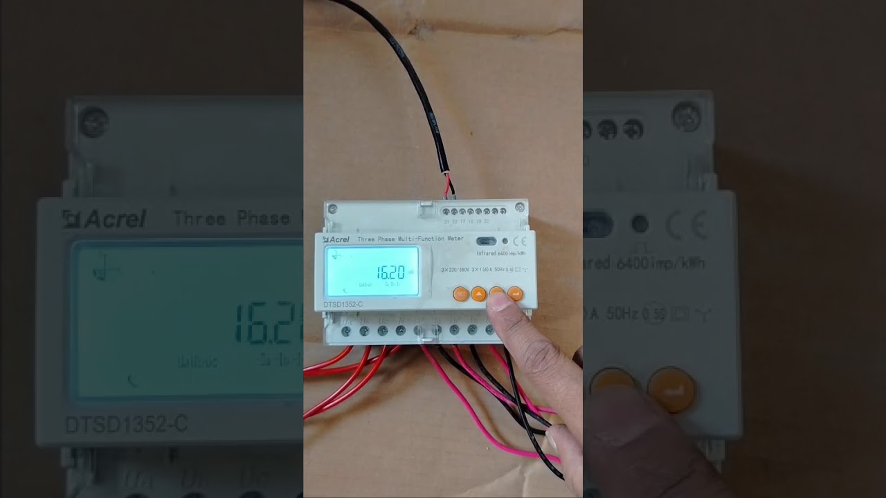
Solis Meter Installation - CT Polarity Part 1
Автор: Electronic Solution
Загружено: 2025-08-31
Просмотров: 104
Описание:
Excellent question. *CT Polarity is the single most common point of failure* during the installation of a Solis smart meter (EPM), and getting it wrong will lead to incorrect data and improper system behavior.
Let's break down exactly what CT polarity means and how to get it right.
---
*Understanding CT Polarity: Two Key Aspects*
CT "polarity" refers to two things, and both must be correct:
1. *Physical Direction:* The physical orientation of the CT clamp on the main power cable.
2. *Wiring Polarity:* The connection of the two small signal wires from the CT to the correct terminals on the meter.
Getting the physical direction wrong is far more common and causes more significant issues.
*1. Physical Direction - The Golden Rule*
Every Current Transformer (CT) clamp has an arrow printed on its body. It often looks like *`P1 → P2`* or just a simple **`→`**.
*The Golden Rule:* The arrow on the CT clamp *MUST* point in the direction of normal power flow. This means it must point *FROM* the grid supply *TOWARDS* your consumer unit (fuse box) and loads.
Think of it like a one-way street for electricity:
`Utility Meter` → `[CT Clamp with Arrow Pointing This Way →]` → `Consumer Unit / Fuse Box` → `House Loads`
#### *Why is this so critical?*
The CT measures two things: the amount of current and the direction it's flowing.
*Correct Direction (→ towards loads):*
When you are *importing* power from the grid, the CT reports a positive value to the meter.
When your solar is generating excess power and you are *exporting* it to the grid, the power flows backward through the CT, which reports a negative value. The inverter understands this and can either record the export amount or ramp down power to stop it.
*Incorrect Direction (← towards grid meter):*
When you are *importing* power, the CT reports a negative value. The system might think you are exporting.
When you are *exporting* power, the CT reports a positive value. The system thinks you are importing a massive amount of power from the grid!
#### *Symptoms of Incorrect Physical Direction:*
On the SolisCloud app, the diagram shows power flowing from your house to the grid, even when you are using lots of power at night.
The inverter's display shows a huge `P-Grid` or `Import` value during the day when you should be exporting.
If you have "Zero Export" enabled, the inverter may shut down or show a "Backflow" or "EPM Fault" alarm because it thinks you are importing power when you're trying to export, creating a confusing logic loop.
---
*2. Wiring Polarity (S1/S2 or K/L Terminals)*
The CT clamp has two small wires coming out of it. These are often labeled *S1* and *S2* (or sometimes K and L). These wires carry the small, measured current signal to the Solis meter.
The Solis meter has corresponding screw terminals, for example:
For CT on Phase 1: *CT1_A* and *CT1_B*
For CT on Phase 2: *CT2_A* and *CT2_B*
And so on for a 3-phase meter.
*Best Practice:*
Connect the *S1* wire from the CT to the *A* terminal on the meter (e.g., CT1_A).
Connect the *S2* wire from the CT to the *B* terminal on the meter (e.g., CT1_B).
*What happens if you reverse these two small wires?*
For most modern meters like the Solis EPM, reversing the S1/S2 wires has the *same effect as reversing the physical CT clamp*. It inverts the reading by 180 degrees.
This means if you accidentally install the CT clamp backward, you could potentially fix it by swapping the S1 and S2 wires at the meter. *However, this is not the recommended solution.* The best and most professional practice is to install the CT clamp in the correct physical direction and wire S1-to-A and S2-to-B. This avoids confusion for anyone who has to service the system later.
---
*Installation & Verification Checklist*
*SAFETY FIRST: This work must be performed by a qualified electrician as it involves live mains cables.*
*Step 1: Identify the Correct Cables*
Locate the main supply cables coming from your utility meter to your main consumer unit.
*Step 2: Clamp the CTs Correctly*
For a single-phase system, clamp the single CT around the *live (phase)* wire. Do not clamp it around the neutral or both live and neutral.
For a three-phase system, clamp one CT on L1, one on L2, and one on L3.
*Crucially, ensure the arrow on every CT clamp points AWAY from the utility meter and TOWARDS the consumer unit.*
*Step 3: Wire to the Meter*
Connect the signal wires from the CT on L1 to the CT1 terminals on the meter (S1 to CT1_A, S2 to CT1_B).
Repeat for L2 (to CT2) and L3 (to CT3) if it's a 3-phase system. Mismatching phases will cause completely erroneous readings.
*Step 4: Verify on the Inverter/App*
Повторяем попытку...
Доступные форматы для скачивания:
Скачать видео
-
Информация по загрузке:


![[TUTO] Installation et configuration de la clé wifi Solis](https://image.4k-video.ru/id-video/gg6EZT8gN9Y)


![[4K FULL HD] Relaxing Water Background | 1 HOUR | Calm Water Wallpaper (No Sound)](https://image.4k-video.ru/id-video/y9PTNTSpGJs)