{1022} E6 Error in Gree Inverter AC || Outdoor PCB Communication Fault Repair
Автор: Haseeb Electronics Urdu
Загружено: 2025-09-13
Просмотров: 1167
Описание:
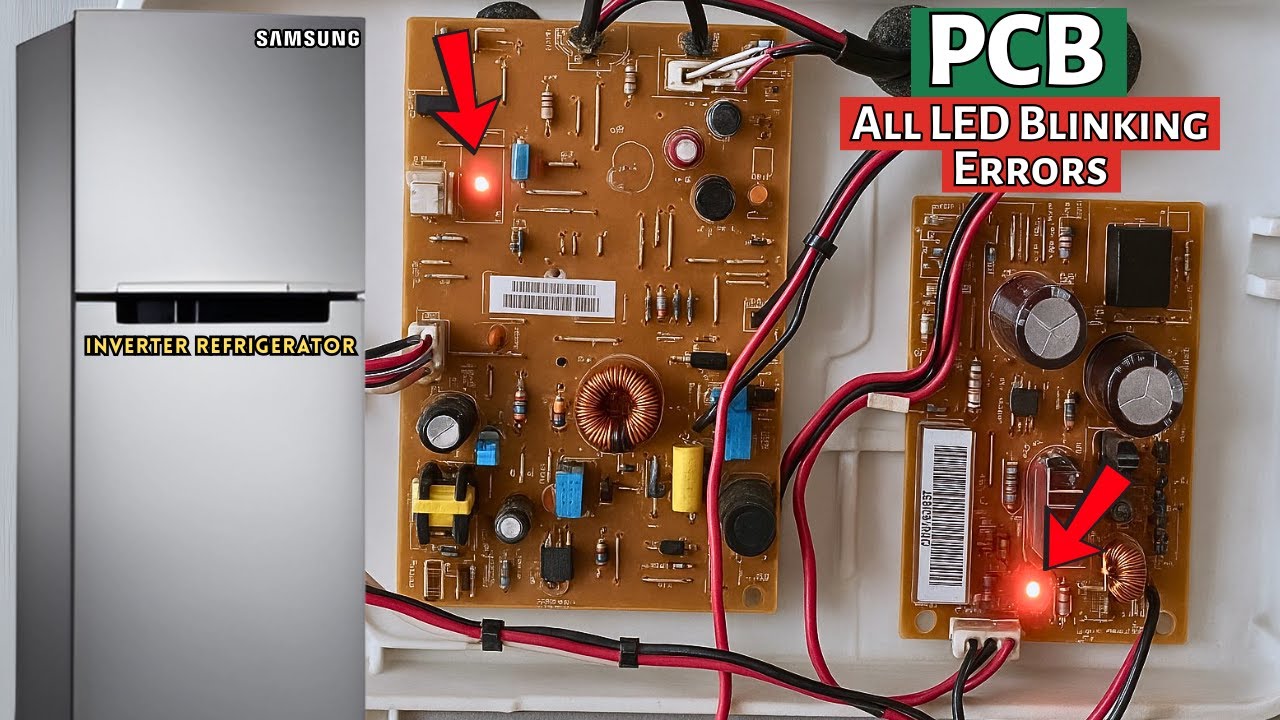
In this video number {1022} E6 Error in Gree Inverter AC || Outdoor PCB Communication Fault Repair. This video repairs a Gree Inverter AC outdoor unit board showing E6 Error (communication fault) between the indoor and outdoor units. We inspect the PCB, find a burnt/weak neutral track, verify surge/EMI/PTC paths, test the bridge rectifier, IGBT, PFC, and IPM (U-V-W), then perform live testing and confirm stable rails (15V / 12V / 5V).
You’ll learn: safety & discharge steps, line/neutral path tracing, how to spot weak copper tracks, and final verification.
If this helped, please Like, Comment, and Subscribe for more repair tutorials on Haseeb Electronics.
we repair a Gree Inverter AC outdoor PCB showing E6 Error (communication fault).
This common error happens when the indoor and outdoor units cannot communicate properly.
We will check the board, identify damaged tracks, and repair them step by step.
🔧 Key Points in this Video:
Meaning of E6 Error in Gree Inverter AC
Causes of communication error between indoor & outdoor units
Inspection of PCB and damaged copper tracks
Repair process with testing & verification
Final solution for E6 Error
📺 More inverter AC repair and PCB fixing tutorials on Haseeb Electronics Channel.
You are Invited to Join Haseeb Electronics
/ @haseebelectronics
You can Follow me on :-
Instagram: / haseebelect
Facebook: https://web.facebook.com/profile.php?...
#haseebelectronics
00:00 Intro & meter setup (safety first)
00:19 Gree Inverter AC Outdorr unit board— E6 error (communication fault)
00:32 Safety warning & power removal
00:42 Discharge/verify capacitor voltage
01:50 Burnt area on PCB identified
02:00 Fuse check (OK)
02:28 Line path: fuse → MOV → EMI → PTC/relay
03:38 Line reaches bridge rectifier (path clear)
04:04 Neutral track open / disconnection found
04:16 Weak copper track → overheating/leakage
04:33 MOV good, capacitor good
04:40 Bridge rectifier diode tests (good)
05:18 DC rail short check (clear)
05:32 IGBT tests (good)
05:54 PFC rectifier test (good)
06:04 IPM UVW tests (good, no shorts)
06:55 Summary so far: only bad PCB track
07:02 Fan driver/IPM check (good)
17:01 Live testing precautions
17:38 AC voltage path & PTC verification
18:01 Communication interlock relay status
18:12 Temporary relay bypass for testing
18:37 Relay engages — confirmed
18:50 Voltage reaches capacitor bank
19:24 Board powers ON — working
19:38 Rails verified: 15V / 12V / 5V
20:45 Root cause: weak track burned open
21:00 Rest of circuit safe (no shorts)
22:02 Outro — Like, comment, thanks
Повторяем попытку...

Доступные форматы для скачивания:
Скачать видео
-
Информация по загрузке: