Civil 3d Assembly, Corridors, Sample Lines, Cross Section Part 2
Автор: Naseer Bhatti
Загружено: 2022-10-14
Просмотров: 1134
Описание:
#civil_3d_assembly_corridor_Sample_lines_Cross_section, #creating_an_assembly_in_civil_3d, #Creating_corridor_in_civil_3d, #Cross_section_in_civil_3d
In the latest YouTube video, we delve into the intricacies of creating and managing sections in Civil 3D. The tutorial covers the step-by-step process of creating styles, selecting styles, and making elevation settings. We also explore the impact of left alignment on profile elevations, including a detailed explanation of key levels and alignments in Civil 3D design. The video concludes with a demonstration of creating cross sections and profiles, providing valuable insights into station elevation disparities and the use of the inquiry tool for elevation checks.
I'd love to hear your thoughts on these advanced Civil 3D techniques. Share your experiences or insights in the comments below! Let's continue the conversation.
Civil 3D Assembly and Corridor Management with Sample Line and Cross Section Part 2
Creating and managing sections and transactions in Civil 3D
• Demonstrating the creation of a style and its selection
• Finishing by making elevation settings
Demonstration of creating styles and calculating levels in Civil 3D Assembly.
• Creating styles and calculating levels based on the demonstrated process.
• Understanding the various options available for selection and their related parameters.
Using elevations in Civil 3D assemblies
• The left target will be elevation for the alignment profile
• The right profile contains the elevation and alignment details
Understanding left alignment and section checking
• Left alignment impacts length and radius along the central line
• File inspection shows differences in lengths on left and right sides
Understanding key levels and alignments in Civil 3D design.
• Level distinctions between central and side lines in relation to given alignments.
• Exploring issues of levels not matching profiles and the reasons behind it.
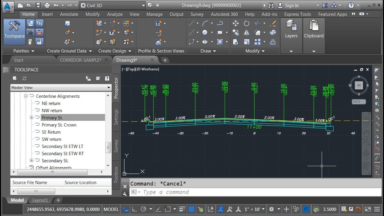
Differences in station elevation explained
• Explaining the difference in station elevation using the example of the left-hand line at 450 station.
• Demonstrating how to use the inquiry tool to check elevation at a specific station.
Cross section elevation does not match the station due to alignment length
• Elevation mismatch due to station assigned based on offset alignment length
• Cross section elevation should match the station of the center line
Creating cross sections and profile in Civil 3D assembly
• Selecting the profile and inquiring about the toll station
• Making cross sections and showing the elevations
Civil 3d Assembly, Corridors, Sample Lines, Cross Section Part 1
• Civil 3d Assembly, Corridors, Sample Lines...
Creating a Code Set Style for Assembly in Civil 3d
• Creating a Code Set Style for Assembly in ...
Marked Point Sub Assemblies in Civil 3d With Additional Points Codes
• Marked Point Sub Assemblies in Civil 3d Wi...
Timecodes
0:00 Creating and managing sections and transactions in Civil 3D
3:10 Demonstration of creating styles and calculating levels in Civil 3D Assembly
5:29 using elevations in Civil 3D assemblies
7:28 Understanding left alignment and section checking
9:53 Understanding key levels and alignments in Civil 3D design
11:17 Differences in station elevation explained
13:44 Cross section elevation does not match the station due to alignment length
15:30 Creating cross sections and profile in Civil 3D assembly
Повторяем попытку...

Доступные форматы для скачивания:
Скачать видео
-
Информация по загрузке: