Servo Motor Controller & Tester Circuit | 555 Timer Project #12
Автор: Elonics - Electronics Projects on Breadboard
Загружено: 2021-03-19
Просмотров: 71243
Описание:
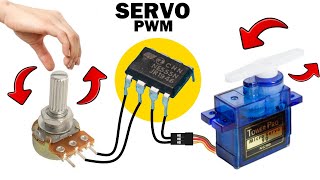
A tutorial on how to make a servo motor controller & tester circuit using 555 timer IC and a few other components. This circuit allows us to manually drive/control any servo motor by pressing buttons or by turning knob of a potentiometer.
Link to the project page and circuit diagram: https://elonics.org/servo-motor-contr...
Components Required
555 Timer IC
Servo Motor
1 PN Diode (I used 1N4148)
2 Momentary Push Button Switches
Resistors: 220K, 56K, 10K
Capacitor: 100nF
Breadboard
Few Breadboard Connectors
(5-9)V Power Supply (Adapt to Servo voltage)
Note: If you wish to control the servo using potentiometer, use a 50K resistor in series with a 1K resistor instead of 56K, 10K resistors and push button switches. Refer to the circuit below for the exact arrangement.
This tutorial is a part of 18 video series on Electronic Projects created using IC 555: • 555 Timer Projects on Breadboard With Work...
-----------------------------------------------------------------------
For more electronics projects, visit: https://elonics.org/
Like our Facebook page: https://fb.me/elonics/
And don't forget to Subscribe!
Повторяем попытку...

Доступные форматы для скачивания:
Скачать видео
-
Информация по загрузке: