4-20 mA Signals Design Rules: Introduction to Bias
Автор: Telugu Automation School
Загружено: 2026-01-04
Просмотров: 143
Описание:
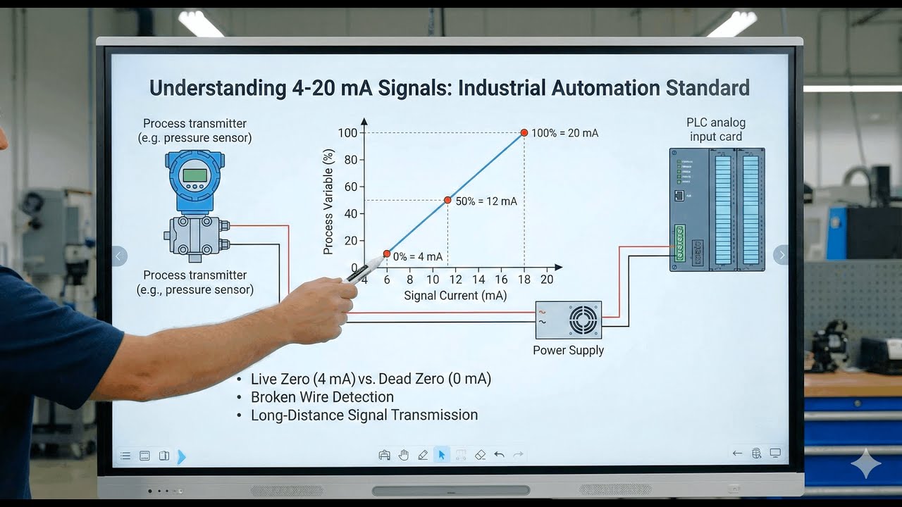
Learn about the design rules followed during the selection of the 4-20 mA signal range for the transmitters, PLC, and automation systems.
🌟FOLLOW US🌟
WhatsApp Channel: https://whatsapp.com/channel/0029VbC1...
Telegram Channel: https://t.me/+lBPg2L-_trEyNjhl
Facebook Page: / teluguautomationschool
....................................................................
💥 JOIN PLC FULL COURSE IN TELUGU HERE:
https://www.udemy.com/course/plc-prog...
📢 JOIN 4-20 mA FULL COURSE IN TELUGU HERE:
https://www.udemy.com/course/4-20-ma-...
🎁 JOIN DCS FULL COURSE IN TELUGU HERE:
https://www.udemy.com/course/distribu...
#design #signals #electricalconcepts
Tags:
4-20mA bias, 4-20mA signal design, live zero current loop, analog signal instrumentation, current loop basics, process transmitters, PLC analog input, DCS analog signals, zero suppression bias, signal integrity, loop design rules, industrial instrumentation training, analog current loop engineering, live zero concept, field transmitter wiring, process control signals, automation engineering basics, instrumentation tutorials, sensor output scaling, control loop fundamentals, industrial current standards, smart transmitter configuration, noise reduction in analog signals, 4-20mA loop error detection, loop troubleshooting techniques, instrumentation videos, control systems learning, 4-20mA explanation, bias in process measurement, engineering beginners guide, industrial signals lecture, automation concepts explained, why 4mA live zero, current based measurement systems
Повторяем попытку...
Доступные форматы для скачивания:
Скачать видео
-
Информация по загрузке:


