Using 3D slicer to create STL file of a fractured pelvis: Learn 3D Slicer in easy steps
Автор: OrthoMatic Times
Загружено: 2017-08-28
Просмотров: 16209
Описание:
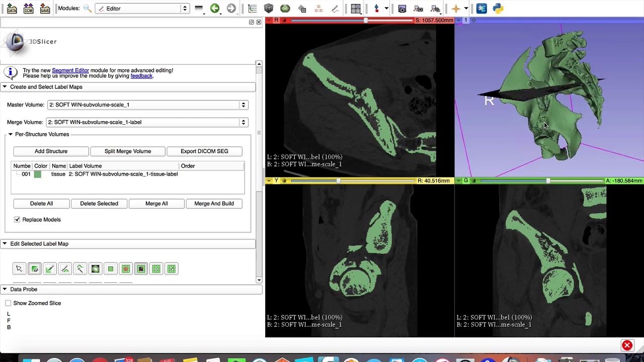
This is the screen recording of the live demo of the workshop conducted by Dr Kshitij Chaudhary & Dr Vaibhav Bagaria from Sir HN Reliance Foundation Hospital, Mumbai, India.
This video demonstrates the steps needed to create a 3D printable STL file from DICOM data. Here, the case shown is a fractured pelvis. The key step is in this process is segmentation. The video also demonstrates how to subtract the femoral head from the STL file.
Following are the steps involved in the process:
STEP 1: IMPORT DICOM IMAGES.
• Click on the “LOAD DICOM DATA” button
• Click import (top left hand corner)
• Select the folder “ANON PELVIS”.
• Choose COPY. Click OK
STEP 2: LOAD THE SOFT TISSUE SERIES
• The import window is divided in three sections. See the bottom section
• Choose “SOFT WIN” series under Study Description
• Click load.
STEP 3: ADJUST THE CONTRAST
• Once you click “LOAD” in the previous step, 4 windows should open, 3 of them with the CT images.
• Red slice – axial, Yellow slice - sagittal, Green slice - Coronal
• Left click the mouse and drag top to bottom to adjust the contrast so that bone is seen best
• Use the click wheel to scroll series
STEP 4: OPEN THE VOLUME RENDERING MODULE AND SELECT ROI.
• In the taskbar on top, go to “MODULES” drop down menu and select Volume Rendering
• Control panel for the volume rendering module opens in the left half.
• Click on Closed Eye icon (next to DISPLAY ROI) so that the eye opens
• A box appears on all slices
• Move the coloured balls on these boxes to narrow down on to region of interest (ROI) for all three windows
• Ensure that you have not over cropped.
Step 5: CROP VOLUME TO THE ROI
• In the Modules dropdown menu, choose all modules, and then Crop Volume
• Select “VOXEL BASED CROPPING” in the pane that appears on the left
• Click on CROP
• Click on the eye symbol in front of ROI visibility to make the boxes disappear.
• Sliders on top of each window containing the CT images are used to scroll through the Slices quickly; ensure that the cropping is correct
STEP 6: OPEN EDITOR
• Click on editor from the Modules drop down menu
• Click okay in the pop up window (Generic anatomy colour)
STEP 7: THRESHHOLD EFFECT TO SELECT BONE.
• The control panel for the editor module should now appear in the pane on your left.
• You’ll see two rows of buttons under “Edit Selected label Map”
• Click on the 5th button in the second row i.e. THRESHOLD EFFECT.
• The slices start blinking with green colour
Scroll down in the Left pane to see the “Threshold Range”
• Keep the upper limit of Threshold range maximum (1440 HU)
• Slide the lower limit to choose 185 Hounsfield units
• Click Apply
• The slices stop blinking green.
STEP 8: CREATE A SURFACE MODEL
• In the left pane, Open “Per-Structure volume” by click the small triangle
• Then click on “Split-Merge Volume”.
• Then click on “Merge and Build”.
• Wait and watch the magic now! It takes time!
• In the right upper window, next to the red slice the model will appear.
• If it does not open, click on the small button to the right of ‘1’
STEP 9: REMOVE UNWANTED AREAS
• In the left pane, under “Edit selected label map”, click on CHANGE ISLAND EFFECT (first row, third last button)
• Click on the Green colour under “ChangeIslandEffect” and select 0 or BLACK from the drop down menu
• Now, click on the gantry in the RED slicer window and click on islands you want coloured black (areas to be excluded from the model)
• Then click on “Split-Merge Volume”.
• Then click on “Merge and Build”.
• The model is now recreated without the CT gantry.
Step 10: SAVE STL FILE
Повторяем попытку...
Доступные форматы для скачивания:
Скачать видео
-
Информация по загрузке:


![CT Scan DICOM Files to 3D [HD]](https://image.4k-video.ru/id-video/Z9ObbjxNCz8)


