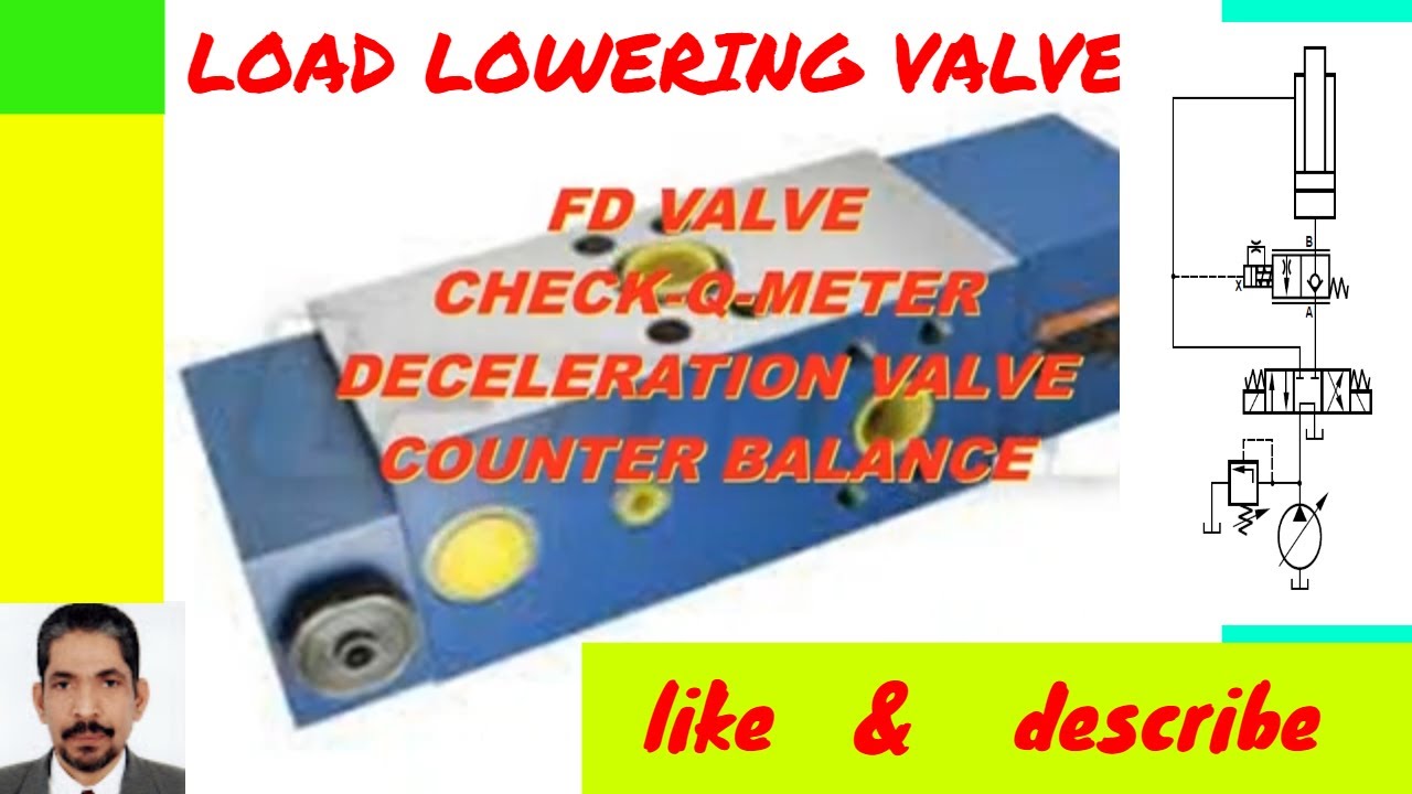
CHECK-Q-METER VALVE -FD-
Автор: Hydraulic - M NAGUIB #HE-TECH
Загружено: 2021-12-21
Просмотров: 1334
Описание:
/ m.naguib.fouda
Check-Q-meter valve
Deceleration valve type FD..
Functions
– Pilot operated check valve, leak-free,
– The check-Q-meter controls the returning flow qV2 in relation
to the flow being directed into the opposite side of the
actuater qV1. With cylinders the area tratio (qV2 = qV1 • ϕ )
has to be taken into account,
– By-pass valve, free-flow in opposite direction,
– Optional built-on secondary pressure relief valve (only for
valve with flange connections).
Functional description, section
Check-Q-meters are used in hydraulic systems to influence the
speeds of hydraulic motors and cylinders independent of the
load (prevents running away). In addition there is an isolator
function for pipe burst safety.
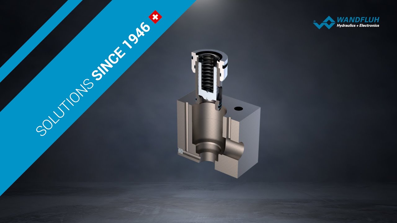
The check-Q-meter comprises basically of the housing (1),
main poppet (2), pilot part (3), pilot spool (4), damping spool
(5) and pilot damping (6).
Lifting the load
With free-flow from A to B the main spool (2) is opened. If the
load pressure fails (e.g. pipe break between the directional
valve and port A) then the main spool (2) immediately closes.
This function is achieved by the connection of the load side (7)
Deceleration valve type FD..
Functions
– Pilot operated check valve, leak-free,
– The check-Q-meter controls the returning flow qV2 in relation
to the flow being directed into the opposite side of the
actuater qV1. With cylinders the area tratio (qV2 = qV1 • ϕ )
has to be taken into account,
– By-pass valve, free-flow in opposite direction,
– Optional built-on secondary pressure relief valve (only for
valve with flange connections).
Functional description, section
Check-Q-meters are used in hydraulic systems to influence the
speeds of hydraulic motors and cylinders independent of the
load (prevents running away). In addition there is an isolator
function for pipe burst safety.
The check-Q-meter comprises basically of the housing (1),
main poppet (2), pilot part (3), pilot spool (4), damping spool
(5) and pilot damping (6).
Lifting the load
With free-flow from A to B the main spool (2) is opened. If the
load pressure fails (e.g. pipe break between the directional
valve and port A) then the main spool (2) immediately closes
with chamber (8).
Lowering the load (circuit examples)
The direction of flow is from B to A. Port A is connected to
tank via the directional valve. The piston rod side of the cylinder
has a flow applied which corresponds to the working
conditions. The relationship between the control pressure at
port X and the load pressure at port B = 1 : 20.
When the control pressure is reached the pre-opening of the
main spool takes place. Via the control spool (4) the pilot stage
(3) is lifted off its seat and chamber (8) is de-compressed via
this drilling and port A to tank. At the same time the load
pressure in port B is no longer applied to chamber (8), this is
due to the longitudinal movement of the pilot stage (3) within
the main spool. The main poppet (2) is thereby unloaded. The
reverse side of the control spool (4) at the main poppet (2),
lies against the collar of the damping spool (5).
The pressure required at port X to open B to A is now only
influenced by the spring in chamber (9). The pressure required
to begin opening the connection B to A is 20 bar; to fully open
the connection 50 bar is required.
The opening cross-section for flow control increases
progressively. It is created by the successive opeining of radial
drillings in the bush and the main poppet (2) land.
The relationship between the control pressure, cracking
pressure and differential pressure determines the flow to the
actuator via the connection of B to A. Thus uncontrolled
running away of the actuator is prevented.
The controlled lowering procedure is not affected even if there
is a pipe burst between the directional valve and port A.
Circuit examples
Differential cylinder
On safety grounds, a closed centre directional valve should
always be used!
Hydraulic motor
So that the holding brake can operate both of the direction all
valve ports have to be connected to port T in the de-energised
position. If the brake is externally unloaded then it is possible to
use a closed centre directional valve in the de-energised
condition.counterbalance valve,
counterbalance valve hydraulic system#sumitomo crane,
counterbalance valve in hydraulic system,
counterbalance valve adjustment,
counterbalance valve on hydraulic motor,
counterbalance valve circuit,
counterbalance valve setting,
counterbalance valve working principle,
counterbalance valve animation,
counterbalance valve application,
counterbalance valve cartridge,
double counterbalance valve,
dual counterbalance valve,
counterbalance valve function,
hydraulic counterbalance valve animation,
sun hydraulics counterbalance valve,
how a counterbalance valve works,
counterbalance valve hydraulic,
counterbalance valve is located,
counterbalance valve is used,
counterbalance valve in hydraulics
Повторяем попытку...
Доступные форматы для скачивания:
Скачать видео
-
Информация по загрузке:


![[EN] Bosch Rexroth: Check and metering E-valve for midi excavators](https://imager.clipsaver.ru/0BBz7rSBQIY/max.jpg)