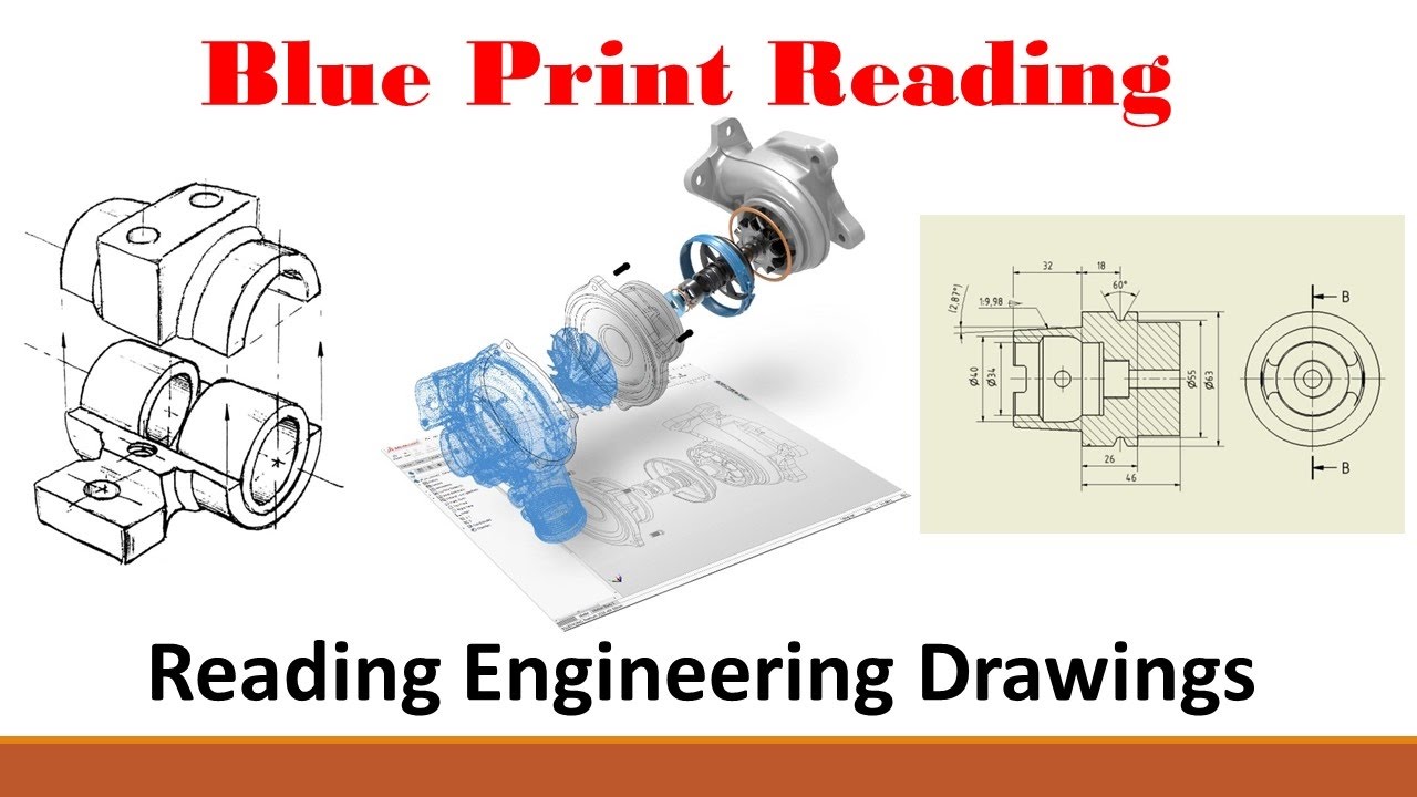
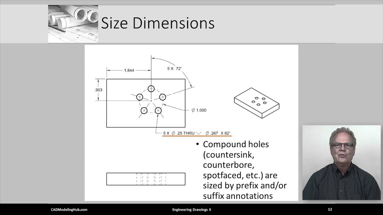
Standard Dimensioning
Автор: CAD Modeling Hub
Загружено: 2016-06-15
Просмотров: 15566
Описание:
This video is called “Standard Dimensioning.” It is the 24th video in the Engineering Design, Modeling and Graphics series, and is brought to you by http://www.cadmodelinghub.com/. This video instructs new and aspiring mechanical engineers, aerospace engineers, and automotive engineers on the ASME and ISO principles and techniques of the standard dimensioning. This video also explains and illustrates proper usage and application of both inch and metric dimensions. We illustrate how to fully dimension different geometric features. Also covered are the special and unique graphic symbols used in the dimensioning process. Yes, the CAD system have auto dimensioning functions, but these generally do not conform to good dimensioning practice, so engineers and designers are still required to either fully dimension their designs or cleanup what has be auto dimensioned. General location and size dimensions are explained, with details being taught for horizontal, vertical, radial, angular, etc. dimensions. What heretofore was done manually, with paper and pencil, is now done by engineers and designers use computer-aided design (CAD), sometimes referred to as 3D CAD, systems to accurately create 3D Designs and to simulate 3D products. It is the creation of correct and accurate engineering drawings that are fully dimensioned using either ISO first angle projection or ASME third angle projection that allows manufacturers to correctly interpret the design’s working drawings. This video introduces correct use and placement of standard inch and metric dimensions.
For more information, the syllabus, expanded course content, assignments, etc. regarding Engineering Design, Modeling and Graphics, visit: http://www.cadmodelinghub.com/eng-des...
LIKE us on FACEBOOK!
/ cadmodelinghub
FOLLOW us on TWITTER!
/ cadmodelinghub
Повторяем попытку...
Доступные форматы для скачивания:
Скачать видео
-
Информация по загрузке:


![Standard [Drawing] Line Types](https://imager.clipsaver.ru/pK3eE25RK8w/max.jpg)